


3. The DC Controller PCB measures the patch pattern using the Registration Patch Sensor Unit (Rear/Front) (UN25/26)
and the result is returned to the Main Controller PCB.
4. The Main Controller PCB compares this measured data with the reference data for ARCDAT control that has been
backed up. The difference by comparison is reflected to the D-half result as the offset value.
● Color Displacement Correction Control
Purpose
To correct color displacement caused by uneven exposure (skew/bent) from the Laser Scanner Unit or uneven rotation of
the drum/ITB
Control description
Color displacement is corrected by forming a patch for color displacement on the ITB and reading the amount of color
displacement by the patch sensor.
1. A patch pattern (short/long) for each color is created on the ITB.
2. This patch pattern is read by the Registration Patch Sensor Unit (Rear/Front) (UN25/26) to detect the amount of color
displacement compared to the reference color (Y).
3. Based on the abovementioned detection result, correction is performed according to the amount of color
displacement.
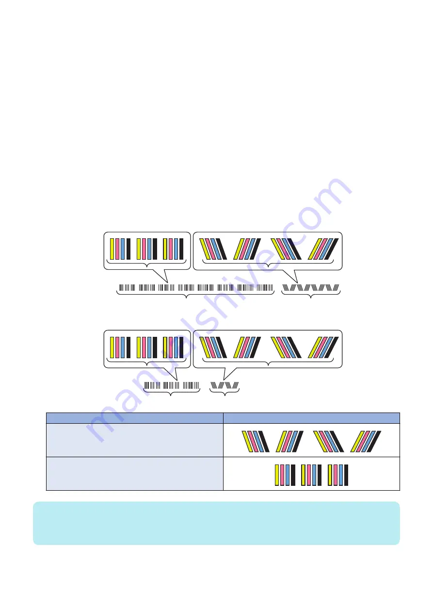
Long patch pattern
8 Set
2 Set
Y M C Bk
Y M C Bk
Short patch pattern
3Set
1Set
Y M C Bk
Y M C Bk
Type
Patch pattern
Patch for correction in horizontal scanning direction
Y M C Bk
Patch for correction in vertical scanning direction
Y M C Bk
NOTE:
Short pattern is normally used as the patch pattern used when performing color displacement correction.
Long pattern is used only in the following cases:
• When Adjustment/Maintenance > Adjust Image Quality > Auto Correct Color Mismatch is executed
2. Technology
80
Summary of Contents for imageRUNNER ADVANCE C3320 Series
Page 1: ...Revision 7 0 imageRUNNER ADVANCE C3330 C3325 C3320 Series Service Manual ...
Page 18: ...Product Overview 1 Product Lineup 7 Features 11 Specifications 17 Parts Name 26 ...
Page 518: ...Error Jam Alarm 7 Overview 507 Error Code 511 Jam Code 617 Alarm Code 624 ...
Page 1020: ...9 Installation 1008 ...
Page 1022: ...2 Perform steps 3 to 5 in each cassette 9 Installation 1010 ...
Page 1024: ...5 6 Checking the Contents Cassette Feeding Unit 1x 3x 2x 1x 9 Installation 1012 ...
Page 1027: ...3 4 NOTE The removed cover will be used in step 6 5 2x 2x 9 Installation 1015 ...
Page 1046: ...When the Kit Is Not Used 1 2 Close the Cassette 2 When the Kit Is Used 1 9 Installation 1034 ...
Page 1068: ... Removing the Covers 1 2x 2 1x 9 Installation 1056 ...
Page 1070: ...3 1x 1x 9 Installation 1058 ...
Page 1083: ...6 7 TP M4x8 2x 2x 9 Installation 1071 ...
Page 1084: ...When Installing the USB Keyboard 1 Cap Cover Wire Saddle 9 Installation 1072 ...
Page 1129: ...9 2x 10 2x 11 9 Installation 1117 ...
Page 1135: ...Remove the covers 1 ws 2x 2 1x 9 Installation 1123 ...
Page 1140: ...2 2x 3 Connect the power plug to the outlet 4 Turn ON the power switch 9 Installation 1128 ...
Page 1176: ... A 2x Installing the Covers 1 1x 2 2x 9 Installation 1164 ...
Page 1190: ...14 Install the Cable Guide to the HDD Frame 4 Hooks 1 Boss 9 Installation 1178 ...


