


5. When the screen indicating the completion of backup is displayed, click [OK], and remove the USB flash drive.
CAUTION:
Causes of backup failure
In the following cases, a message indicating that the backup has failed and its cause are displayed. Take appropriate
measures.
• No USB flash drive is connected.
• Two or more USB flash drives are connected.
• Not enough space on USB flash drive.
• The connected USB flash drive is read-only.
• No key.
CAUTION:
Storing the USB flash drive
Advise users of the following.
• Store the USB flash drive under lock and key.
• Do not store the backup files of the TPM keys in a USB flash drive at a location to which the general public has access,
such as on a server.
NOTE:
Name of the backup file of the TPM key
The serial number of the machine is automatically assigned to the name of the backup file.
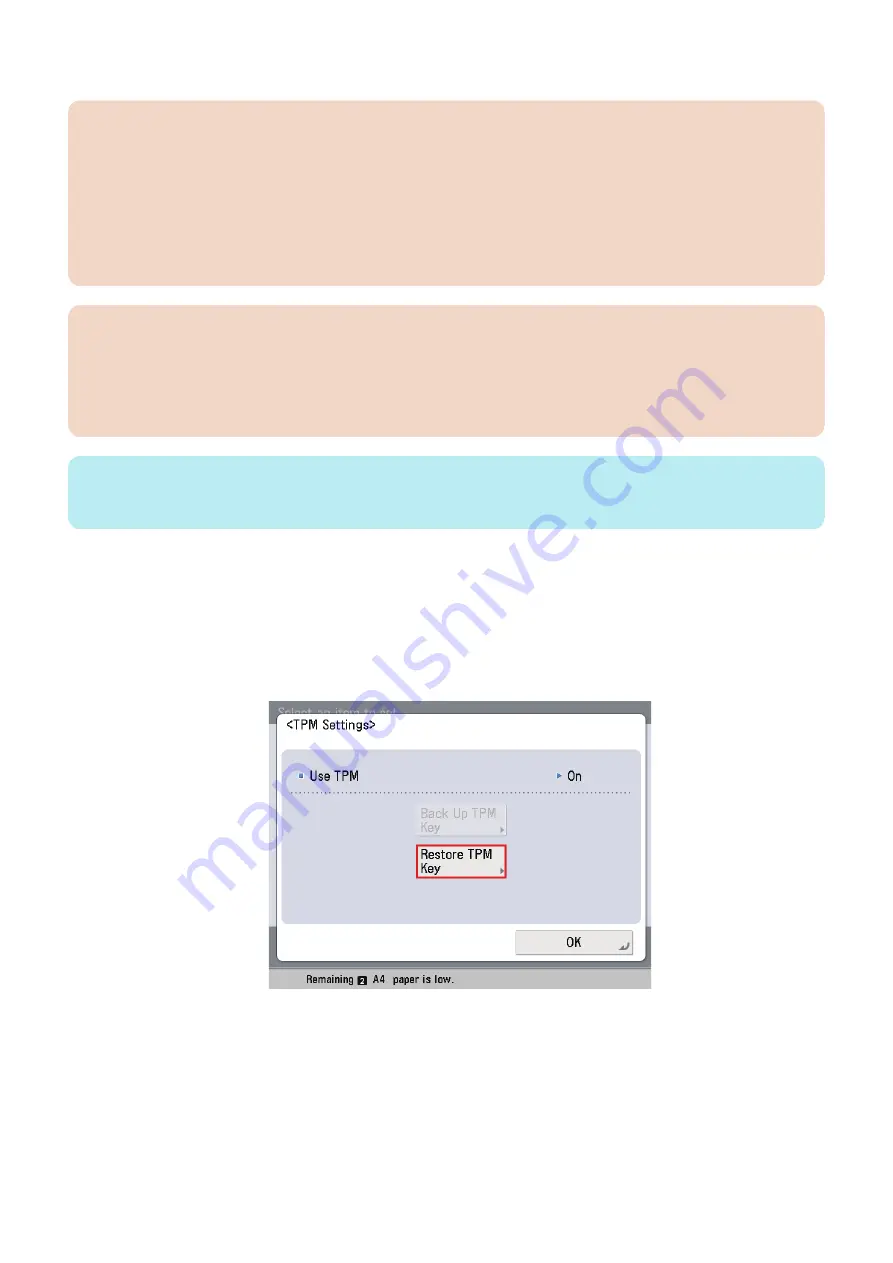
● Restoration of TPM key
The operation is almost the same as that of backup.
Differences:
When the restoration is completed, restart (turning OFF and then ON the Main Power Supply Switch) is required.
1. Connect the USB flash drive containing the saved TPM key.
2. Execute Management Settings > Data Management > TPM Settings, and click [Restore TPM Key].
3. Enter the password set at backup operation.
4. When the screen appears confirming the start of restoration, click [OK]. Restoration starts.
2. Technology
48
Summary of Contents for imageRUNNER ADVANCE C3320 Series
Page 1: ...Revision 7 0 imageRUNNER ADVANCE C3330 C3325 C3320 Series Service Manual ...
Page 18: ...Product Overview 1 Product Lineup 7 Features 11 Specifications 17 Parts Name 26 ...
Page 518: ...Error Jam Alarm 7 Overview 507 Error Code 511 Jam Code 617 Alarm Code 624 ...
Page 1020: ...9 Installation 1008 ...
Page 1022: ...2 Perform steps 3 to 5 in each cassette 9 Installation 1010 ...
Page 1024: ...5 6 Checking the Contents Cassette Feeding Unit 1x 3x 2x 1x 9 Installation 1012 ...
Page 1027: ...3 4 NOTE The removed cover will be used in step 6 5 2x 2x 9 Installation 1015 ...
Page 1046: ...When the Kit Is Not Used 1 2 Close the Cassette 2 When the Kit Is Used 1 9 Installation 1034 ...
Page 1068: ... Removing the Covers 1 2x 2 1x 9 Installation 1056 ...
Page 1070: ...3 1x 1x 9 Installation 1058 ...
Page 1083: ...6 7 TP M4x8 2x 2x 9 Installation 1071 ...
Page 1084: ...When Installing the USB Keyboard 1 Cap Cover Wire Saddle 9 Installation 1072 ...
Page 1129: ...9 2x 10 2x 11 9 Installation 1117 ...
Page 1135: ...Remove the covers 1 ws 2x 2 1x 9 Installation 1123 ...
Page 1140: ...2 2x 3 Connect the power plug to the outlet 4 Turn ON the power switch 9 Installation 1128 ...
Page 1176: ... A 2x Installing the Covers 1 1x 2 2x 9 Installation 1164 ...
Page 1190: ...14 Install the Cable Guide to the HDD Frame 4 Hooks 1 Boss 9 Installation 1178 ...


