background image

System Management Mode of the imageRUNNER 3300/2800/2200

III

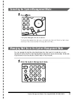
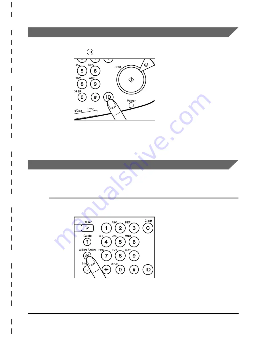
Canceling the System Management Mode

1

Press

(ID).

The System Management mode is canceled.

The System Management mode is also canceled even when Auto Clear has taken place, 
returning to the screen specified to display after Auto Clear.

Managing Mail Box in the System Management Mode

You can operate the mail box documents stored by other users. For example, you can 
operate a mail box that the user has forgotten its password, erase unnecessary documents, 
or get access to box documents of other users in case of need.

1

Enter the System Management mode.

Summary of Contents for imageRUNNER 3300

Page 1: ...Read this guide first Please read this guide before operating this equipment After you finish reading this guide store it in a safe place for future reference ENG Reference Guide Reference Guide...

Page 2: ...ng Guide For Basic Mail Box Function Use For Convenient Mail Box Function Use Mail Box Function Guide For Fax Use For Convenient Fax Use Facsimile Guide For Remote UI Use Remote UI Guide For Setting U...

Page 3: ...Routine Maintenance Troubleshooting Handling Options Appendix Contains the Appendices and Index Chap 1 Please read this chapter Chap 2 Chap 3 Chap 4 Chap 5 Chap 6 Chap 7 Chap 8 Considerable effort has...

Page 4: ...rogram that promotes energy saving through the use of computers and other office equipment The program backs the development and dissemination of products with functions that effectively reduce energy...

Page 5: ...H of the U S Food and Drug Administration implemented regulations for laser products on August 2 1976 These regulations apply to laser products manufactured from August 1 1976 Compliance is mandatory...

Page 6: ...rformance of procedures other than those specified in the manual may result in hazardous radiation exposure CANON INC 3 30 2 SHIMOMARUKO OHTA KU TOKYO JAPAN MANUFACTURED THIS PRODUCT CONFORMS WITH DHH...

Page 7: ...e of Your Product and the Use of Images xxviii Operation of the Machine and Terms Used in This Manual xxix Chapter 1 Before You Start Using This Machine About the Installation Location and Handling 1...

Page 8: ...ment ID and Password 1 37 Operations After Turning the Power On 1 37 Operations After Using Copy Functions 1 39 Placing Originals 1 40 Orientation of Originals 1 41 Placing an Original on the Platen G...

Page 9: ...Setting a Standard Mode for Local Printing 3 26 Changing the Language Displayed on the Touch Panel Display 3 28 Reversing the Display 3 29 Returning the Common Settings to Their Defaults 3 30 Setting...

Page 10: ...enance Loading Paper 5 2 Loading Paper in the Paper Drawers 5 2 Adjusting a Paper Drawer to Hold a Different Paper Size 5 6 Adding Toner 5 9 Routine Cleaning 5 15 Cleaning the Platen Glass Rear Side o...

Page 11: ...velope Feeder Attachment to Hold a Different Type of Envelope 7 23 Feeder DADF H1 7 27 Parts and Their Functions 7 27 Clearing Paper Jams in the Feeder 7 28 Replacing the Stamp Cartridge When the Fax...

Page 12: ...rations After Using Copy Fax or Mail Box Functions 7 82 Department ID Management When Using the Control Card 7 83 Chapter 8 Appendix Specifications 8 2 Main Unit 8 2 Feeder DADF H1 8 4 Cassette Feedin...

Page 13: ...operations that may lead to death or injury to persons if not performed correctly In order to use the machine safely always pay attention to these warnings CAUTION Indicates a caution concerning opera...

Page 14: ...model or options are not displayed on the touch panel display The keys which you should press are marked with as shown below When multiple keys can be pressed on the touch panel display all keys are m...

Page 15: ...e the machine a fire or electrical shock may result Necklaces and other metal objects Cups vases flowerpots and other containers filled with water or liquids If these items are dropped or spilled insi...

Page 16: ...s on the machine as they may tip over or fall resulting in personal injury Do not install the machine in the following locations A damp or dusty location A location which is exposed to direct sunlight...

Page 17: ...the power cord or pull on or excessively bend it as this could cause electrical damage and result in a fire or electrical shock Do not insert or unplug the power plug with wet hands as this may result...

Page 18: ...shock Do not use power cords other than the provided power cord as this may result in a fire or electrical shock As a general rule do not use an extension cord Using an extension cord may result in a...

Page 19: ...than 120 V AC as this may result in a fire or electrical shock Always grasp the plug portion when unplugging the power plug Pulling on the power cord may expose or snap the core wire or otherwise dam...

Page 20: ...ises or emits smoke heat or unusual smells immediately turn off the main power switch and unplug the power plug from the outlet Then contact your service representative Continued use of the machine in...

Page 21: ...ater liquids or flammable substances alcohol benzene paint thinner etc inside the machine If these items come into contact with a high voltage area inside the machine this may result in a fire or elec...

Page 22: ...sher while the machine is printing as this may result in personal injury Do not place your hand in the part of the tray where stapling is performed while a finisher is attached as this may result in p...

Page 23: ...he machine is plugged in for a long time in a damp dusty or smoky location dust can build up around the plug and become damp This may cause a short circuit and result in a fire Clean the machine using...

Page 24: ...ome into contact with your hands or clothing as this will dirty your hands or clothing If they become dirty wash them immediately with cold water Washing with warm water will set the toner and make it...

Page 25: ...paper in places exposed to open flames as this may cause the toner or paper to ignite and result in burns or a fire When discarding the toner cartridges put the cartridges in a bag to prevent the ton...

Page 26: ...ARNING The laser unit inside the machine emits laser light Under no circumstances open the cover of the laser unit or remove the label attached to the cover If the laser light escapes from the machine...

Page 27: ...g procedure IMPORTANT Make sure that the main power is turned ON and the machine is neither printing nor scanning before starting a periodic inspection of the breaker If a malfunction occurs after a p...

Page 28: ...does not go to the OFF position side repeat step 1 If the breaker lever does not go to the OFF position side despite carrying out the above procedure two or three times contact your service representa...

Page 29: ...ON position I side IMPORTANT If the breaker lever stops between ON and OFF move the breaker lever to OFF then back to ON 5 Press the main power switch to the ON position I side 6 Fill in the check sh...

Page 30: ...of using your product to scan print or otherwise reproduce any particular document and or of the use of the images scanned printed or otherwise reproduced you should consult in advance with your lega...

Page 31: ...ou can also print from this machine using a function other than the Copy function In this machine these operations take place in a complex way so that not only copies but also various kinds of prints...

Page 32: ......

Page 33: ...System Manager 1 13 Using Other Useful Functions 1 14 Parts and Their Functions 1 17 External View 1 17 Internal View 1 19 Control Panel Parts and Functions 1 20 Checking the Counter 1 22 Checking th...

Page 34: ...Originals 1 40 Orientation of Originals 1 41 Placing an Original on the Platen Glass 1 42 Placing Originals in the Feeder DADF H1 1 44 Making Prints Using the Stack Bypass 1 47 Using the Stack Bypass...

Page 35: ...alling the Machine in the Following Locations Avoid locations which are subject to extremes of temperature and humidity either low or high For example avoid installing the machine near water faucets h...

Page 36: ...ed period of time in a poorly ventilated room or when making a large quantity of prints be sure to ventilate the room to make the working environment as comfortable as possible Avoid locations where a...

Page 37: ...inting can adversely affect the operation of such equipment Avoid installing the machine near televisions radios or similar electronic equipment The machine might interfere with sound and picture sign...

Page 38: ...connected Do not plug the machine into a multi plug power strip Doing so might cause a fire The power cable may become damaged if it is often stepped on or if heavy objects are placed on it Continued...

Page 39: ...ine Some parts inside the machine are subject to high voltages and temperatures Take adequate precaution when inspecting the inside of the machine Do not carry out any inspections not described in thi...

Page 40: ...ed period of time for example during the night turn the control panel power switch off There may be an accident or a defect with the hard disk in the machine causing loss destruction or alternation of...

Page 41: ...e initial screen the first screen shown when the machine is turned on from the Additional Functions screen The initial screen can be the Copy Fax Mail Box or System Monitor screen Setting Specificatio...

Page 42: ...f and Clear Message Board are not displayed For details of the Custom Fax Settings Printer Settings Report Settings Communications Setting Network Settings and Remote UI On Off functions refer to the...

Page 43: ...p 3 34 Daily Timer At the time and day of the week set with the daily timer the control panel power switch automatically turns off To reactivate the machine press the control panel power switch NOTE...

Page 44: ...gs up a guide screen with information about the various features that are available with your machine Usage Guide Pressing Guide after selecting a function brings up a guide screen with an explanation...

Page 45: ...Press Various originals You can display simple explanations of the various types of originals using or Press Done to return to the Various Originals Menu screen To return the display to the Guide Men...

Page 46: ...e board in which the message appears in the Job Print monitor area NOTE For details of how to erase the message board see Erasing the Message Board Clear Message Board on p 4 25 Using Other Useful Fun...

Page 47: ...py waiting time depending on the selected copy mode NOTE The job duration time is not displayed for the Transparency Interleaving Cover Sheet Insertion Different Size Originals Rotate Collating and Ro...

Page 48: ...als Cover sheet Insertion Double Staple or Hole Punch is selected while Auto paper selection is set or when Transparency Interleaving XY Zoom or Free size paper setting is selected See the Copying Gui...

Page 49: ...ne 1 Parts and Their Functions External View 2 1 3 4 5 6 7 8 1 2 3 4 5 6 7 8 When Feeder DADF H1 Finisher J1 and Cassette Feeding Unit W1 are attached When Feeder DADF H1 Saddle Finisher G1 Inner 2way...

Page 50: ...r 20 lb bond 80 g m2 Also the Envelope Feeder Attachment B1 option can be attached 6 Paper drawer 2 Holds up to 500 sheets of paper 20 lb bond 80 g m2 7 8 Paper drawer 3 4 Paper drawers of the Cassett...

Page 51: ...and non standard size paper stock See Making Prints Using the Stack Bypass on p 1 47 8 Main power switch Press to the I side to turn the power on See Main Power and Control Panel Power on p 1 24 9 Br...

Page 52: ...switch sub power supply Press to turn the control panel ON or OFF When set to OFF the machine is in the Sleep mode 8 Clear key Press to clear incorrectly entered values or characters 9 Stop key Press...

Page 53: ...s F Interrupt key Press to interrupt a continuous copying job when you need to make priority copies G Additional Functions key Press to set additional functions H Guide key Press to display explanatio...

Page 54: ...Before You Start Using This Machine 1 Checking the Counter You can check counter totals of copy and print jobs 1 Press Counter Check on the control panel The counter totals are shown in the touch pan...

Page 55: ...nables you to check the version of this machine and get information about the options attached 1 Press Counter Check on the control panel 2 Press Device Config The Device Configuration screen is displ...

Page 56: ...er outlet WARNING Never remove or insert the power plug with wet hands This can cause an electrical shock 2 Press the power switch to ON I side The main power switch is located on the right side of th...

Page 57: ...er off if the FAX Board is attached Transmission Receive of fax cannot be done when the power is turned off NOTE In the case above the Standard settings are selected The standard copy settings are as...

Page 58: ...ns If the message You must insert a control card appears Insert a control card NOTE See Card Reader C1 on p 7 80 If the message Enter the Department ID and Password using the numeric keys appears Ente...

Page 59: ...switch to cancel the Sleep mode and resume normal machine operations NOTE The machine can receive and print documents from a personal computer even when it is in the Sleep mode Faxes can also be rece...

Page 60: ...r with the printer and fax function Refer to the following instructions Setting up and Connecting to the Network See the Network Guide Installing the Printer Driver See the PS PCL Driver Guide Date an...

Page 61: ...screen retaining the programmed settings in the Additional Functions screen Press to cancel the function mode that is either being set or has already been set in screens other than the Additional Fun...

Page 62: ...hese functions in combination with the presently set function mode A tick appears on the screen for some keys when you press the keys CAUTION Press the touch panel keys gently with a finger Do not pre...

Page 63: ...ng the Brightness of the Touch Panel Display If the touch panel display is difficult to view use the display contrast dial on the control panel to adjust its brightness NOTE To make the touch panel br...

Page 64: ...enter characters using the alphabet keys displayed in the touch panel display as described below Entering Alphabet Characters Example Enter Canon 1 Press Entry Mode to select Alphabet Each press of E...

Page 65: ...press Entry Mode before you press OK to select Other NOTE If you make a mistake when entering characters use or to position the cursor and Backspace to delete the character Then enter the correct cha...

Page 66: ...ore You Start Using This Machine Entering Special Characters Example Enter 1 Press Entry Mode to select Other Each press of Entry Mode switches the entry mode between Alphabet and Other 2 Press or to...

Page 67: ...press OK to select Alphabet NOTE If you make a mistake when entering special letters use or to position the cursor and Backspace to delete the character Then enter the correct character You can also d...

Page 68: ...et the inch entry function to On from the Common Settings of the Additional Functions screen See Setting Inch Input on 3 12 You can then enter inches once you press Inch in a screen requiring numeric...

Page 69: ...to enter the Department ID or to insert the control card may be displayed even if you are already using the machine Follow the instructions of the message Operations After Turning the Power On After...

Page 70: ...achine 2 Press ID The Basic Features screen of the selected function appears on the touch panel display If the Department ID and or Password that you entered are wrong the message This number has not...

Page 71: ...ain enter the Department ID and Password If you do not press ID after finishing your copy operations any subsequent copies will be totaled under the Department ID which you previously entered When cop...

Page 72: ...the feeder all at once during basic Copy Mail Box operations use the Job Build mode See the Copying Guide and the Mail Box Function Guide Platen glass Place the originals on the platen glass when scan...

Page 73: ...depending on the mode you have set LTR and STMT size originals can be placed either vertically or horizontally However the scanning speed for horizontally placed originals is somewhat slower than for...

Page 74: ...TE The machine automatically detects the size of following originals 11 x 17 LGL LTR LTRR and STMTR 1 Lift up the feeder platen glass cover IMPORTANT This machine is equipped with an open close sensor...

Page 75: ...size originals using the platen glass you need to set LTRR STMT Original Selection in Additional Functions See Distinguishing LTRR size and STMT size Originals on p 3 19 3 Gently lower the feeder pla...

Page 76: ...Feeder DADF H1 Place a stack of originals in the feeder and press Start The machine automatically scans them into memory Two sided originals can also be automatically scanned as two sided image data...

Page 77: ...other originals which might not feed smoothly Transparencies and other highly transparent originals If the feeder rollers are soiled from scanning an original written with pencil perform the Feeder C...

Page 78: ...originals from the original output area to avoid paper jams NOTE The scanned originals are output face down to the original output area You can place different size originals i e LTR and 11 x 17 STMT...

Page 79: ...ng this paper horizontally may cause blurred images When making two sided prints select the Two sided mode Not selecting the correct mode may cause creases on the print depending on the moisture absor...

Page 80: ...he loaded paper Proceed to Step 6 NOTE If the paper size loaded in the stack bypass is different from the paper size stored in the Standard Stack Bypass Settings set the Stack Bypass Standard Settings...

Page 81: ...tack bypass Make sure that the height of the paper stack does not exceed the limit mark Align the required number of sheets of paper with the slide guides The surface that you want to print on must be...

Page 82: ...ke five or so envelopes and loosen them as shown then stack them together Repeat this step 5 times Place the envelopes on a clean level surface and spread them out by hand in the direction of the arro...

Page 83: ...and the sealed or glued portion stay flat IMPORTANT Do not print on the underside of the envelopes If the envelopes become filed with air flatten them by hand before loading them in the envelope feed...

Page 84: ...Orientation Priority is set to On load the envelopes as shown below 4 Select the paper size and press Next If envelopes are loaded press Envelope and specify the envelope type Then press OK OK and pro...

Page 85: ...tandard Settings to Off IMPORTANT Set the paper size to the same size as the paper loaded in the stack bypass If Standard Paper for Stack Bypass is set to On you can load only the registered paper typ...

Page 86: ...ure is not necessary NOTE When there is no reserved job continue the procedure from step 2 8 Press Start When printing documents stored in a mail box press Start Print Copying starts NOTE If heavyweig...

Page 87: ...er is being fed from the stack bypass for the current job and that you are reserving 11 x 17 plain paper to be fed from the stack bypass for the next reserved job IMPORTANT If Stack Bypass Standard Se...

Page 88: ...series paper size press A B size If Stack Bypass Standard Settings is set to On the screen which shows the paper size type selected beforehand will be displayed See Setting the Standard Paper for the...

Page 89: ...ified paper when its turn comes to print NOTE The specified paper size is displayed when its turn comes to print Even when setting reserved print settings if paper is loaded in the stack bypass specif...

Page 90: ...1 Making Prints Using the Stack Bypass 1 58 Before You Start Using This Machine 8 Select the paper type and press OK The machine starts printing...

Page 91: ...Fax in addition to the Copy function You can operate these functions together Multi function Operation The following table presents details of multi function operations Copy Mail box Scanning data Pr...

Page 92: ...next job after performing the previous job Available TX scanning included includes a reservation of the direct sending Fax Printer Scanning data TX RX Printing of Auto RX Documents Receiving data Prin...

Page 93: ...unch paper we recommend that you set the Image Orientation Priority to On in the Additional Functions screen See the Copying Guide 5 Some types of tracing paper cannot be used 6 3 Hole Punch paper can...

Page 94: ...Stack Bypass on p 1 47 Paper drawers 3 4 and Paper Deck are optional Paper Size Length x Width Available Loading Place Paper Set Place Paper drawer 1 3 Paper drawer 2 4 Stack Bypass Paper Deck 11 x 1...

Page 95: ...r Flow of Checking Changing Operations 2 2 Checking Canceling a Job in the Spooler 2 4 Checking Print Job Details 2 7 Canceling a Reserved Job 2 8 Canceling from the Touch Panel Display 2 8 Canceling...

Page 96: ...ssed By displaying the History List you can confirm a job that has already been processed Also it is possible to print a report of fax transmission reception from the System Monitor screen From the Sy...

Page 97: ...ocessed or waiting to be processed press Status To see jobs that have already been processed press Log NOTE The status of each icon displayed in the screen is as follows Operating Waiting Error Cancel...

Page 98: ...yed only when the Printer Kit optional is attached Operations such as checking or canceling spool jobs are possible only when Use Spooler is set to On For details see the Network Guide 1 Press System...

Page 99: ...2 Flow of Checking Changing Operations 2 5 Checking Job and Device Status 2 Press Print 3 Select Spool Status 4 Press...

Page 100: ...Select the job you want to cancel press Cancel Press Yes If you do not want to cancel the job press No To check the job details Select Status or Log Select the job you want to view more details about...

Page 101: ...as the date and time entered and the number of pages 1 Press System Monitor select Copy Fax or Print 2 Press Status or Log select the job you want to view more details about and press Details 3 Check...

Page 102: ...served job in several ways Canceling from the Touch Panel Display 1 Press Cancel in the screen shown below which appears while the machine is scanning printing or waiting to print a document The selec...

Page 103: ...el on the touch panel display which appears during printing 2 Select the job to be canceled from the list and press Cancel V You cannot select multiple documents and cancel them all at once When cance...

Page 104: ...the System Monitor Screen You can cancel a job while it is waiting to be processed or during printing 1 Press System Monitor and select the Job Type 2 Press Status 3 Select the job to be canceled and...

Page 105: ...2 11 Checking Job and Device Status 4 Press Yes If you do not want to cancel the job press No NOTE The canceled document is displayed as NG on the Print Log screen 5 Press Done The display returns to...

Page 106: ...rity printing for a job the machine starts printing the job once the currently printing document is completed 1 Press System Monitor and press Print 2 Press Status 3 Select the document for priority p...

Page 107: ...Device Status 2 Handling Print Jobs Sent from a Computer You can temporarily stop a print job sent from a computer or skip an error when a print error occurs 1 Press System Monitor and press Print 2...

Page 108: ...You can continue the print job even when a print error has occurred by pressing Auto Continue depending on the type of print error However the print output may not be the same as expected When printi...

Page 109: ...2 Handling Print Jobs Sent from a Computer 2 15 Checking Job and Device Status 7 Press Done The display returns to the Basic Features screen...

Page 110: ...b number To print these documents you need to enter the correct password This prevents other people who do not know the password from observing the contents of the print job IMPORTANT If the main powe...

Page 111: ...password and press OK Enter the same password originally assigned from the computer The machine becomes ready to print the document To cancel printing press Cancel The machine starts printing If there...

Page 112: ......

Page 113: ...Standard Paper for the Stack Bypass 3 24 Setting a Standard Mode for Local Printing 3 26 Changing the Language Displayed on the Touch Panel Display 3 28 Reversing the Display 3 29 Returning the Common...

Page 114: ...s The Remote UI Guide Additional Function Available settings Applicable page Common Settings Initial Function Copy Mail Box Fax Set System Monitor Screen as initial function On Off Set Device as the d...

Page 115: ...fset Collate Group Offset Group Staple Corner With the Saddle Finisher G1 Inner 2way Tray A1 Do not Collate Collate Offset Collate Group Offset Group Staple Corner Double With the Inner 2way Tray A1 D...

Page 116: ...Adjustment Cleaning Zoom Fine Adjustment X Y 0 1 0 to 1 0 in 0 1 increments P 3 39 Saddle Stitch Position Adjustment 2 0 mm to 2 0 mm 0 mm in 0 25 mm increments P 3 40 Exposure Recalibration 9 Steps...

Page 117: ...ax Comment 32 characters max Department ID Management P 4 6 Department ID Management On Off ID Password Store Edit Erase Limit Impress Print Totals Clear Clear All Totals Print List Accept Jobs with U...

Page 118: ...n Off Photo Mode On Off Standard Settings Store Initialize Initialize Copy Settings Initialize Custom Fax Settings User Settings Standard Key Settings All Modes No settings Unit telephone Numerals Uni...

Page 119: ...d Page Footer On Off Printer Settings Select Cassette Switch A D Each On Off Receive Reduction On Off Two sided Print On Off 2 On 1 Log On Off File Settings Memory Box Store Set Confidential Relay Bat...

Page 120: ...to scroll to the desired screen and make the required settings When the or should be pressed the indication is displayed in this manual Selecting the Initial Function at Power ON You can specify whic...

Page 121: ...ction screen appears If you select Fax The Fax Basic Features screen appears When using the System Monitor screen as the initial screen Select On and press OK The System Monitor screen is displayed wh...

Page 122: ...Function or Selected Function and press OK To display the screen set under Initial Function after Auto Clear is performed press Initial Function For example if Copy is set under Initial Function and...

Page 123: ...unction occurs e g paper jam or operational error Job Done Tone After the job has been completed output stapled stored in a Mail Box or faxed NOTE The default setting is On for all tones The volume of...

Page 124: ...h Input You can display the key for entering values in inches in the numeric entry screens NOTE The default setting is On 1 Call up the desired screen as follows 2 Select On or Off and press OK 3 Pres...

Page 125: ...opy or of the image when receiving a fax Auto Drawer Switching ADS If a paper drawer runs out of paper during a continuous printing job the machine automatically selects another paper drawer with the...

Page 126: ...er eligible for APS ADS press On To make the paper drawer ineligible for APS ADS press Off The number of each paper drawer indicates the following locations Stack bypass Paper drawer 1 Paper drawer 2...

Page 127: ...en you set Consider Paper Type to Off paper will be fed from another paper drawer when paper runs out during printing if the same paper size is loaded in that paper drawer When you select Printer the...

Page 128: ...ss OK Load the same type of paper as set in each paper drawer NOTE For details of paper types see Available Paper Stock on p 1 61 Paper drawer 1 Paper drawer 2 Paper drawer 3 option Paper drawer 4 opt...

Page 129: ...the Basic Features screen NOTE The paper types stored here are displayed when selecting paper in each mode as shown below Setting the Functions Keys as Keys to Reactivate the Machine You can set Copy...

Page 130: ...ne is in the Sleep mode NOTE In the following cases the energy consumption when the machine enters the Sleep mode is High regardlles of this setting For details such as setting each function see the F...

Page 131: ...this procedure The specified mode is set and the display returns to the Basic Features screen Distinguishing LTRR size and STMT size Originals You can designate the way the machine handles LTRR size o...

Page 132: ...select Use STMT Format The machine detects the original as STMT size 3 Press Done Repeat this procedure The specified mode is set and the display returns to the Basic Features screen Setting a Dedicat...

Page 133: ...he case that the Saddle Finisher G1 is not attached Tray C can only be assigned to a single function which no other tray is assigned to When the Saddle Finisher G1 is attached the print is output to T...

Page 134: ...y may start depending on the settings The default settings are as follows Copy 1 Priority Printer 2 Other 3 1 2 and 3 indicate priority sequence 1 Call up the desired screen as follows 2 Select the pr...

Page 135: ...ougata 4 This section describes how to specify the type of envelopes and which cassette they are to be loaded in IMPORTANT When the Envelope Feeder Attachment option is not attached this procedure is...

Page 136: ...tically to the paper drawers and the paper deck This setting is useful if you always set paper of the same size and type NOTE When using the stack bypass as a paper source for the Copy Mail Box and Fa...

Page 137: ...tings to Suit your Needs 3 Select the paper size and press Next NOTE To select inch size paper press A B size To select free size paper press Free Size To select envelope press Envelope and select the...

Page 138: ...prints with the standard Local Print settings when you merge multiple documents NOTE The default settings are as follows indicates factory default setting Paper Select Paper source Auto Copies 1 Finis...

Page 139: ...es from 1 set to 2 000 sets Finisher Set the type of collating Two sided Print Set whether or not to perform two sided printing Erase Document After Printing Set whether or not to erase a document aft...

Page 140: ...ricted and not be able to be entered To enable all characters to be entered set to Off Even when Language Switch is set to On there are some languages which cannot be displayed The default setting is...

Page 141: ...on the touch panel display If you are finding it hard to make out what is being shown on the display using this function may make things clearer NOTE The default setting is OFF 1 Call up the desired s...

Page 142: ...function you can return the common settings to their defaults initial settings 1 Call up the desired screen as follows 2 Select Yes To cancel initialization select No The screen shown below is display...

Page 143: ...me You can set the current date and time The date and time set here is also used as the time setting when required for functions GMT The time at the Greenwich Observatory in England is called GMT Gree...

Page 144: ...from 2000 to 2038 Examples MAY 6 0506 7 05 a m 0705 11 18 p m 2318 NOTE If you make a mistake when entering values press Clear and enter the values again When setting the Time Zone Settings Press Time...

Page 145: ...o specify each of them Enter the time using and and press OK Press End Date and make the settings in the same way as the above NOTE When you make the Daylight Saving Time settings the machine automati...

Page 146: ...eatures screen Setting the Time Taken to Initiate Auto Sleep After Finishing Operations If the machine is not operated no keys are pressed for a certain period of time the control panel power switch a...

Page 147: ...me Taken for the Display to Return to the Basic Features Screen After Finishing Operations If the machine is not operated no keys are pressed for a certain period of time the display returns to the Ba...

Page 148: ...specified mode is set and the display returns to the Basic Features screen Setting the Time Taken for the Unit to Quiet Down After the Last Task This machine enters the Quiet mode after a specified a...

Page 149: ...ified mode is set and the display returns to the Basic Features screen Setting the Time that the Unit s Power Turns Off on Different Days of the Week You can set the time that the machine automaticall...

Page 150: ...he time in 24 hour clock as four digits without a space Examples 7 05 a m 0705 11 18 p m 2318 If you make a mistake when entering the time choose the day of the week again and enter the four digit num...

Page 151: ...is displayed in this manual Fine adjusting the Zoom When Differences in Original Image and Print Image Occur When you print a copy or a document in a mail box and a slight difference occurs between t...

Page 152: ...is attached slight position differences in the saddle stitch position may occur With this function you can compensate for such differences IMPORTANT This function can only be set when the Saddle Fini...

Page 153: ...ecified mode is set and the display returns to the Basic Features screen Adjusting the Standard Exposure Adjusts the exposure adjustment scale to calibrate differences in exposure Perform this adjustm...

Page 154: ...OFF If the service call message containing an error code shown below appears be sure to turn the main power switch ON again After that if the same message appears when paper is output contact your se...

Page 155: ...lect On or Off and press OK To disable Staple Offset press Off To enable Staple Offset press On 3 Press Done Repeat this procedure The specified mode is set and the display returns to the Basic Featur...

Page 156: ...Interface Adapter Printer Kit and FAX Board is attached Printing the Contents of the Fax Settings You can print the lists of the Address Book List 1 and 2 the Group Destination List and the User s Dat...

Page 157: ...Suit your Needs 3 Press Address Book List 1 4 Press Yes If you do not want to print press No The screen below appears and printing starts When printing is completed Print Completed appears To close t...

Page 158: ...print the user s data list in the Network Settings when the Network Interface Adapter is attached 1 Call up the desired screen as follows 2 Press Network under Print List When both the FAX Board and...

Page 159: ...to Suit your Needs 3 Press User s Data List 4 Press Yes If you do not want to print press No The screen below appears and printing starts When printing is completed Print Completed appears To close th...

Page 160: ...rinting the Contents of the Printer Settings When the Printer Kit is attached you can print the contents of the printer setting 1 Call up the desired screen as follows 2 Press Printer under Print List...

Page 161: ...Storing Settings to Suit your Needs 4 Press Yes If you do not want to print press No When printing is completed the screen returns to step 3 5 Press Done Repeat this procedure The specified mode is se...

Page 162: ......

Page 163: ...anagement 4 6 Storing the Department ID and Password and Impression Limit 4 6 Changing the Password and Impression Limit 4 11 Erasing the Department ID and Password 4 14 Checking and Printing Counter...

Page 164: ...ager ID For details on how to enter the characters see Entering Characters from the Touch Panel Display on p 1 32 The maximum number of characters you can assign for a name contact and comment is 32 a...

Page 165: ...D You cannot store a System Manager ID with only the number 0 such as 0000000 NOTE You can delete the number you entered by pressing Clear 4 Press System Password use numeric keys to enter a number of...

Page 166: ...em Manager Settings 4 4 System Manager Settings 5 Press E mail Address and enter an e mail address for the system manager 6 Press Contact Information and enter where to contact the system manager 7 Pr...

Page 167: ...ations of System Manager Settings System Manager Settings 4 5 System Manager Settings 8 Once you have completed all settings press OK 9 Press Done Repeat this procedure The display returns to the Basi...

Page 168: ...e Password Settiing Function Restrictions Setting the Impression Limit for each department IMPORTANT This function switches to Card ID Management when the Control Card option is attached Card ID Manag...

Page 169: ...4 7 System Manager Settings 2 Press On If you do not want to store a password proceed to step 3 3 Press Store Dept ID Password NOTE For details concerning print totals see Checking and Printing Count...

Page 170: ...e a Department ID with only the number 0 such as 0000000 NOTE When a password is not stored you can use this machine by entering only the Department ID 6 Press Impression Limit and enter the desired v...

Page 171: ...nagement 4 9 System Manager Settings 7 Press OK 8 Press Limit Functions 9 Select functions to which to apply Department ID Management other than Copy and press OK Department ID Management is not appli...

Page 172: ...on Limit and press Done To make the Impression Limit set in the step 6 effective press Limit Impress Limit Impress cannot be selected for a particular department 11 Press OK NOTE When you select On De...

Page 173: ...tment ID and Password on p 1 37 Changing the Password and Impression Limit The following instructions describe how to change the Password and Impression Limit you have stored 1 Call up the desired scr...

Page 174: ...ress OK To change Impression Limit press Impression Limit and enter the desired value using numeric keys Then press OK You cannot store a password with only the number 0 such as 0000000 NOTE The numbe...

Page 175: ...Department ID Management is enabled See Entering the Department ID and Password on p 1 37 7 Press Done Repeat this procedure When the screen below appears enter the Department ID and Password NOTE Fo...

Page 176: ...ment ID Management with Card Reader C1 you cannot erase the Department ID 1 Call up the desired screen as follows When the System Manager ID Password is set enter the System Manager ID and System Pass...

Page 177: ...Press Yes If you do not want to erase the Department and its settings press No The selected Department and its settings are erased 5 Press Done 6 Press OK NOTE When you select On Department ID Manage...

Page 178: ...ID and Password see Entering the Department ID and Password on p 1 37 Checking and Printing Counter Information You can display and print a list of the paper count for each department 1 Call up the d...

Page 179: ...correspondent with a stored Department ID unknown ID If you only want to check the counter Press or to display the desired Department and check the print totals If you want to print the displayed lis...

Page 180: ...On Department ID Management is enabled See Entering the Department ID and Password on p 1 37 6 Press Done Repeat this procedure When the screen below appears enter the Department ID and Password NOTE...

Page 181: ...le to delete print totals for a particular department 1 Call up the desired screen as follows When the System Manager ID Password is set enter the System Manager ID and System Password after pressing...

Page 182: ...ment 4 20 System Manager Settings 4 Select Yes If you do not want to erase the counter press No 5 Press Done 6 Press OK NOTE When you select On Department ID Management is enabled See Entering the Dep...

Page 183: ...37 Specifying Whether or Not to Accept Print Jobs of Unknown ID You can specify whether or not to print documents from a computer not correspondent with a stored Department ID NOTE Accept jobs with u...

Page 184: ...Department ID is enabled See Entering the Department ID and Password on p 1 37 3 Select On or Off and press OK If you want to print from a computer not correspondent with a stored Department ID press...

Page 185: ...System Manager Settings 4 Press Done Repeat this procedure When the screen below appears enter the Department ID and Password NOTE For details of how to enter the Department ID and Password see Enteri...

Page 186: ...d after pressing System Settings Then press ID 2 Press Device Name and Location enter the name of this machine and the location where this machine is placed press OK The maximum number of characters w...

Page 187: ...ge board settings are done from the Remote UI however erasing a message board can be done from the main unit as well 1 Call up the desired screen as follows When the System Manager ID Password is set...

Page 188: ...desired screen as follows When the System Manager ID Password is set enter the System Manager ID and System Password after pressing System Settings Then press ID 2 Select On or Off and press OK NOTE...

Page 189: ...oading Paper in the Paper Drawers 5 2 Adjusting a Paper Drawer to Hold a Different Paper Size 5 6 Adding Toner 5 9 Routine Cleaning 5 15 Cleaning the Platen Glass Rear Side of Platen Glass Cover 5 16...

Page 190: ...per in the Paper Drawers When the selected paper has run out or the selected paper drawer runs out of paper during printing a screen prompting you to load paper appears on the touch panel display CAUT...

Page 191: ...Routine Maintenance 1 Press and release the button of the paper drawer in which you want to load paper 2 Grip the handle and pull out the paper drawer until it stops 3 Open a package of paper and rem...

Page 192: ...on 4 Turn the opened surface of the paper stack over and place it in the paper drawer Even out the edges of the paper stack Load the paper stack against the right wall of the paper drawer When loading...

Page 193: ...ot to get your fingers caught as this may result in personal injury IMPORTANT Never place paper or any other items in the open part of the paper drawer next to the paper stack Doing so may cause paper...

Page 194: ...es can be loaded in the paper drawers Paper drawers 1 3 LGL LTR LTRR STMT and STMTR Paper drawers 2 4 11 x17 LGL LTR LTRR STMT and STMTR Paper drawers 3 and 4 can be used when the Cassette Feeding Uni...

Page 195: ...guides are adjusted correctly for the loaded paper size 4 Set the size switch to match the paper being loaded INCH For Inch series paper A B For A B series paper If you change the setting of the size...

Page 196: ...etting the paper size dial correctly results in the display of an incorrect paper size on the touch panel display Also it may cause paper jams dirty prints or make the inside of the machine dirty To p...

Page 197: ...hrow used toner cartridges into open flames as this may ignite the toner remaining inside the cartridge and result in burns or a fire IMPORTANT Use only the toner cartridge recommended for use on this...

Page 198: ...5 Adding Toner 5 10 Routine Maintenance 1 Open the front cover of the main unit 2 Pull the blue lever down 3 Grip the blue handle on the toner box Pull out the toner box until it stops...

Page 199: ...s shown below and rock it several times to the left and right 5 Place the toner cartridge on the toner box as shown below and push it in as far as possible 6 Push the toner cartridge down to lock it i...

Page 200: ...rtridge knob until the stop sign appears 8 Lightly tap the top of the toner cartridge to cause the toner to empty into the toner box 9 Push the black toner box handle back to its original position The...

Page 201: ...he toner box WARNING Do not throw used toner cartridges into open flames as this may ignite the toner remaining inside the cartridge and result in burns or a fire CAUTION When removing a used toner ca...

Page 202: ...5 Adding Toner 5 14 Routine Maintenance 11 Push the toner box back to its original position 12 Pull the blue lever up to its original position 13 Close the front cover of the main unit...

Page 203: ...ff the main power switch and unplug the power plug Failure to do so may result in a fire or electrical shock Do not use alcohol benzene paint thinner or other solvents for cleaning Doing so might resu...

Page 204: ...ass cover following the procedure below IMPORTANT If the platen glass or the rear side of the platen glass cover is dirty the original may not be scanned cleanly or the size of the original may be det...

Page 205: ...g rubbing off the originals and onto the roller Perform this feeder cleaning procedure to clean the feeder scanning area white plate and roller IMPORTANT If the feeder scanning area is dirty it may re...

Page 206: ...cover holding the knob in the front 4 Clean the transparent plastic part of the middle cover with a cloth dampened with water 5 Close the middle cover CAUTION When closing the cover be careful not to...

Page 207: ...ver CAUTION When closing the cover be careful not to get your fingers caught as this may result in personal injury 7 Open the feeder 8 Clean the feeder scanning area platen glass and the metal part lo...

Page 208: ...OTE Adjustment Cleaning is made up of several screens Select the desired item by pressing or When or shoud be pressed the indications is displayed in this manual It takes about 20 seconds to clean the...

Page 209: ...screen Roller Cleaning If dirt appears on printed paper clean the roller in the main unit as the need arises NOTE Adjustment Cleaning is made up of several screens Select the desired item by pressing...

Page 210: ...22 Routine Maintenance 2 Press Start To cancel Roller Cleaning press Cancel While the roller is being cleaned the screen below appears 3 Press Done Repeat this procedure The display returns to the Ba...

Page 211: ...mables Paper Stock In addition to plain paper 11 x 17 LGL LTR and STMT transparencies dedicated to this machine labels and other types of paper stock are available For details consult your service rep...

Page 212: ...ause the toner to ignite and result in burns or a fire IMPORTANT Store toner cartridges in a cool location away from direct sunlight The recommended storage conditions are temperature below 86 F and h...

Page 213: ...riginals when they are sent For the Fax function Options Cassette U1 You can adjust this cassette to suit the paper size you want to load See Adjusting a Paper Drawer to Hold a Different Paper Size on...

Page 214: ...enance Cassette V1 You can adjust this cassette to suit the paper size you want to load See Adjusting a Paper Drawer to Hold a Different Paper Size on p 5 6 Locations to set paper drawer 1 and 3 Avail...

Page 215: ...Clearing Paper Jams in the Exit Slot 6 11 Clearing Paper Jams in the Upper Right Cover 6 15 Clearing Paper Jams in the Stack Bypass 6 17 Clearing Paper Jams in a Paper Drawer 6 19 Frequently Occurrin...

Page 216: ...dly appears on the touch panel display until the paper jam is entirely cleared Example of Screen Indicating the Location of the Paper Jam You can confirm the location of the paper jam When you select...

Page 217: ...y to prevent the toner on the paper from scattering and entering your eyes or mouth If toner enters your eyes or mouth wash them immediately with cold water and consult a physician 1 Inspect all areas...

Page 218: ...ptional units see the instructions on the following pages Cassette Feeding Unit W1 See Clearing Paper Jams in the Cassette Feeding Unit W1 on p 7 5 Paper Deck L1 See Clearing Paper Jams in the Paper D...

Page 219: ...inisher J1 on p 7 37 Saddle Finisher G1 See Clearing Paper Jams in the Saddle Finisher G1 on p 7 52 Clearing Paper Jams in the Saddle Stitcher Unit on p 7 54 Clearing Paper Jams in the Puncher Unit on...

Page 220: ...e feeder the print operation restarts If there is remaining paper to be removed a screen indicating how to clear that paper jam appears on the touch panel display Repeat the procedure from step 1 Clea...

Page 221: ...ove any paper remaining in the fixing unit 4 Turn the green knob 2 places in the direction of the arrow and remove any jammed paper CAUTION The parts located around the knob are subject to high temper...

Page 222: ...position 6 Close the front cover of the main unit CAUTION When closing the cover be careful not to get your fingers caught as this may result in personal injury 7 Follow the instructions on the touch...

Page 223: ...ne shown below appears on the touch panel display Check where the jam occurred and follow the procedure described below and the procedure that appears on the touch panel display to remove the jammed p...

Page 224: ...cover of the main unit CAUTION When closing the cover be careful not to get your fingers caught as this may result in personal injury 5 Follow the instructions on the touch panel display NOTE For det...

Page 225: ...ne shown below appears on the touch panel display Check where the jam occurred and follow the procedure described below and the procedure that appears in the touch panel display to remove the jammed p...

Page 226: ...6 Clearing Paper Jams 6 12 Troubleshooting 2 Open the lower left cover of the main unit 3 Move the green lever in the direction of the arrow 4 Remove any jammed paper...

Page 227: ...ject to high temperatures When removing jammed paper take care not to touch anything in this area except the lever 6 Turn the green knob 2 places in the direction of the arrow and remove any jammed pa...

Page 228: ...closing the cover be careful not to get your fingers caught as this may result in personal injury 8 Return the green lever to its original position 9 Close the front cover CAUTION When closing the co...

Page 229: ...ilar to the one shown below appears on the touch panel display Check where the jam occurred and follow the procedure described below and the procedure that appears on the touch panel display to remove...

Page 230: ...ee p 7 9 is attached reattach the paper deck to the main unit CAUTION When closing the cover be careful not to get your fingers caught as this may result in personal injury 4 Follow the instructions o...

Page 231: ...stack bypass a screen similar to the one shown below appears on the touch panel display Check where the jam occurred and follow the procedure described below and the procedure that appears on the tou...

Page 232: ...ams 6 18 Troubleshooting 3 Close the stack bypass 4 Open the upper right cover of the main unit When the Paper Deck L1 option see p 7 9 is attached move the paper deck away from the main unit 5 Remove...

Page 233: ...njury 7 Follow the instructions on the touch panel display NOTE For details of the screen indicating how to clear the paper jam see Screen Shown When There Is a Paper Jam on p 6 2 Clearing Paper Jams...

Page 234: ...he main unit When the Paper Deck L1 option See p 7 9 is attached move the paper deck away from the main unit 2 Remove any jammed paper 3 Press and release the paper drawer release button of the paper...

Page 235: ...ull out the paper drawer 5 Remove any jammed paper 6 Return the paper drawer to its original position CAUTION When returning the paper drawer to the original position be careful not to get your finger...

Page 236: ...e main unit When the Paper Deck L1 option see p 7 9 is attached reattach the paper deck to the main unit 8 Follow the instructions on the touch panel display NOTE For details of the screen indicating...

Page 237: ...proper working order follow the procedure below to clean the static charge eliminator NOTE If paper jams occur frequently make sure that the size set on the paper size dial of the drawers matches the...

Page 238: ...sh 4 Clean the groove of the static charge eliminator as shown below Insert the brush of the static charge eliminator cleaner into the groove and carefully move the brush back and forth in the groove...

Page 239: ...6 Frequently Occurring Paper Jams 6 25 Troubleshooting 6 Return the brush to its original position 7 Close the front cover of the main unit...

Page 240: ...it will go See Loading Paper on p 5 2 Load LTR size paper Cause The paper drawer loaded with the best paper size selected by the Automatic Paper selection mode is not inserted into the machine Remedy...

Page 241: ...ou from making prints Remedy Remove paper from the machine following the guidance messages on the touch panel display See Clearing Paper Jams on p 6 2 Waste toner is full Cause The waste toner box is...

Page 242: ...e job or operation does not complete correctly check the End Code and perform the necessary operations according to the End Code displayed You can check the End Code in the Details screen under Log in...

Page 243: ...fied mail box Remedy Check the available memory of the main unit and delete unwanted documents in the memory boxes If there are a large number of unwanted documents delete those in the specified mail...

Page 244: ...d about 3 700 originals LTR size Canon Standard Chart Standard setting scanned in the standard mode 1 Follow this procedure If the message asking whether to print the original pages scanned into memor...

Page 245: ...t in electrical shock CAUTION Always grasp the plug portion when unplugging the power cord Pulling on the power cord may expose or snap the core wire or otherwise damage the power cord If the cord is...

Page 246: ...n power switch off Allow at least three seconds before turning the main power switch back on 2 If the machine still does not operate normally follow the procedure below and contact your service repres...

Page 247: ...ll Message 6 33 Troubleshooting NOTE When you contact your service representative have the following information on hand Product name Details of the malfunction The error code displayed on the touch p...

Page 248: ...ON check that the breaker is not OFF or between ON and OFF If the breaker is OFF contact your service representative Do not switch the breaker back ON WARNING If the breaker is in the OFF position do...

Page 249: ...der Attachment to Hold a Different Type of Envelope 7 23 Feeder DADF H1 7 27 Parts and Their Functions 7 27 Clearing Paper Jams in the Feeder 7 28 Replacing the Stamp Cartridge When the Fax Function I...

Page 250: ...ctions 7 73 Tray Functions 7 74 Clearing Paper Jams in the Inner 2way Tray A1 7 74 Copy Tray F1 7 78 Parts and Their Functions 7 78 Card Reader C1 7 80 Operations Before Using Copy Fax or Mail Box Fun...

Page 251: ...nfiguration The following options can be attached to the machine 1 Feeder DADF H1 2 Finisher J1 3 Cassette Feeding Unit W1 4 Inner 2way Tray A1 5 Paper Deck L1 6 Saddle Finisher G1 7 Puncher Unit K1 8...

Page 252: ...o the machine you have two additional sources of paper for printing jobs Up to 500 sheets of paper can be loaded in each drawer of the cassette feeding unit Parts and Their Functions 1 Drawers Each dr...

Page 253: ...e do not allow necklaces bracelets or other metal objects to touch the inside of the machine as this may result in burns or electrical shock When removing paper which has become jammed inside the mach...

Page 254: ...r of the main unit When the Paper Deck L1 option is attached move the paper deck away from the main unit see p 7 9 before opening the cover 2 Remove any jammed paper 3 Press and release the paper draw...

Page 255: ...out the paper drawer 5 Remove any jammed paper 6 Return the paper drawer to its original position CAUTION When returning the paper drawer to its original position be careful not to catch your fingers...

Page 256: ...the paper deck to the main unit see p 7 9 CAUTION When closing the cover be careful not to get your fingers caught as this may result in personal injury 8 Follow the instructions on the touch panel d...

Page 257: ...ndicator is lit you may not be able to open the paper deck In this case press the control panel power switch to reactivate the machine and press the Open button NOTE The paper size of the Paper Deck i...

Page 258: ...bjects to touch the inside of the machine as this may result in burns or electrical shock When removing paper which has become jammed inside the machine take care not to allow the toner on the jammed...

Page 259: ...7 Paper Deck L1 7 11 Handling Options 2 Remove any jammed paper 3 Press the Open button to open the paper deck 4 Remove any jammed paper...

Page 260: ...main unit be careful not to get your fingers caught as this may result in personal injury 6 Follow the instructions on the touch panel display NOTE For details of the screen indicating how to clear th...

Page 261: ...aper take care not to cut your hands on the edges of the paper IMPORTANT Rewrap any remaining paper in its original package and store it in a dry place away from direct sunlight NOTE For high quality...

Page 262: ...urled or wrinkled paper Transparencies Paper which has been copied on using a digital full color copier do not copy on the reverse side either Paper which has been printed on using a thermal transfer...

Page 263: ...ts and Their Functions When the Envelope Feeder Attachment is attached to Paper Drawer 1 1 Left guide Align to the length of envelopes being loaded 2 Envelope receptacle 3 Back width guide 4 Front wid...

Page 264: ...s with clasps or windows Envelopes with seals closed with glue or other substances Envelopes with holes or perforations Envelopes with specially coated surfaces Envelopes made of surface treated color...

Page 265: ...nvelopes contact your service representative NOTE To use envelopes other than COM10 refer to Adjusting the Envelope Feeder Attachment to Hold a Different Type of Envelope on p 7 23 Only the upper most...

Page 266: ...rface and spread them out by hand in the directions of the arrows Repeat this step five times IMPORTANT Take particular care to spread the envelopes out in the direction they will be fed 3 Hold down t...

Page 267: ...opes the side with the flap If the envelopes become filled with air flatten them by hand before loading them in the envelope feeder attachment Loading Envelopes This section explains how to load envel...

Page 268: ...drawer until it stops 3 Squeeze the lever on the left guide as shown below and pull out the left guide as far as possible 4 Load the envelopes with the printing surface face down as shown below While...

Page 269: ...ette When the Saddle Finisher G1 is attached print by setting the Image Orientation Priority to Off in the Additional Functions screen Do not allow the number of envelopes height loaded in the cassett...

Page 270: ...TION When returning the paper drawer to its original position be careful not to get your fingers caught as this may result in personal injury IMPORTANT Never place paper or any other items in the open...

Page 271: ...Different Type of Envelope This section explains how to load envelopes of types other than the one currently specified in the Additional Functions screen 1 Press and release the button of the paper d...

Page 272: ...V 1 This allows the envelope stored to ENV 1 in the Set Envelope Cassette setting in the Additional Functions screen to be loaded When selecting ENV 2 Set the size switch to ENV 2 This allows the enve...

Page 273: ...and remove all envelopes already loaded in the drawer 6 Loosen the two screws fixing the front width guide of the cassette 7 As shown below push down on the envelope receptacle and move the front widt...

Page 274: ...e in place using the screws 9 Adjust the back width guide of the cassette as in steps 7 and 8 10 Load the envelopes 11 After checking the size switch store the envelope type on the Additional Function...

Page 275: ...so be automatically reversed to make two sided copies from two sided originals IMPORTANT If the paper delivery slot is blocked printing may not be performed correctly Therefore do not place objects in...

Page 276: ...er metal objects to touch the inside of the machine as this may result in burns or electrical shock When removing paper which has become jammed inside the machine take care not to allow the toner on t...

Page 277: ...7 Feeder DADF H1 7 29 Handling Options 2 Remove any jammed originals 3 Open the middle cover holding the knob in the front 4 Turn the knob and remove any jammed original...

Page 278: ...he cover be careful not to get your fingers caught as this may result in personal injury 6 Once you have removed all of the jammed original close the upper cover of the feeder CAUTION When closing the...

Page 279: ...Open the feeder and remove any jammed originals 8 Close the feeder 9 Follow the instructions on the touch panel display NOTE For details of the screen indicating how to remove the paper jam see Screen...

Page 280: ...alled Originals sent by fax via the feeder attached to this machine can be stamped to indicate that they have been sent Replace the stamp cartridge when this mark is faint or is no longer visible 1 Op...

Page 281: ...ew stamp cartridge in until it clicks using tweezers IMPORTANT Make sure that the stamp cartridge is not protruding from the surface Set the stamp cartridge properly or it may cause paper jams 4 Gentl...

Page 282: ...r Staple mode cannot be set NOTE When feeding large size paper such as 11 x 17 LGL or LTRR pull out the auxiliary tray Parts and Their Functions 1 Front cover Open this cover to replace the staple cas...

Page 283: ...sets to make them easier to handle NOTE The output tray moves down when each set of paper is delivered When the delivered paper reaches the stacking limit of the tray printing stops temporarily Remov...

Page 284: ...and LTRR Remove all the paper from the output tray before stapling NOTE Copies are stapled in the following places When an original is placed on the platen glass When originals are placed in the feede...

Page 285: ...ther metal objects to touch the inside of the machine as this may result in burns or electrical shock When removing paper which has become jammed inside the machine take care not to allow the toner on...

Page 286: ...s 2 Remove any jammed paper 3 Lift the inner guide and remove any jammed paper 4 Close the upper left cover of the finisher CAUTION When closing the cover be careful not to get your fingers caught as...

Page 287: ...g Options 5 Open the front cover of the finisher 6 Remove any jammed paper 7 Close the front cover of the finisher CAUTION When closing the cover be careful not to get your fingers caught as this may...

Page 288: ...see Screen Shown When There Is a Paper Jam on p 6 2 Replacing the Staple Case in the Stapler Unit When the finisher is almost out of staples and the staple case must be replaced a display similar to...

Page 289: ...ng Options 2 Pull out the staple cartridge holding it by its left and right sides 3 Pull out the empty staple case holding it by its left and right sides Place the staple cartridge as shown below and...

Page 290: ...e case IMPORTANT Use only the special staple case intended for use with this machine NOTE Only one staple case can be inserted at a time 5 Remove the seal fixing the staples by pulling it straight out...

Page 291: ...t in personal injury NOTE When you close the cover the stapler unit automatically performs a dry stapling operation several times to reposition the staples Removing Jammed Staples from the Stapler Uni...

Page 292: ...7 Finisher J1 7 44 Handling Options 1 Open the front cover of the finisher 2 Pull out the protruding staple cartridge holding it by its left and right sides 3 Lower the knob of the staple cartridge...

Page 293: ...J1 7 45 Handling Options 4 Remove all of the staples that slide from the staple case 5 Return the knob of the staple cartridge to its original position 6 Push the staple cartridge back firmly into th...

Page 294: ...s may result in personal injury NOTE When you close the cover the stapler unit automatically performs a dry stapling operation several times to reposition the staples Consumables Use only the staple c...

Page 295: ...ed Tray for Each Function on p 3 20 2 Auxiliary tray 3 Upper cover Open to remove jammed paper See Clearing Paper Jams in the Saddle Finisher G1 on p 7 52 4 Punch waste tray Take this out when discard...

Page 296: ...set Mode This function outputs papers shifted to the front NOTE These functions shift each set of output paper about 3 4 20mm before delivery when the Collate function or Group function has been set w...

Page 297: ...1 x 17 and LGL size or 50 for LTR and LTRR size stapling will not be performed Only Collating will be performed If the machine stops during stapling and Load staples is displayed it means that almost...

Page 298: ...ds may appear differently according to the type of paper and or the number of sheets to be saddle stitched Punch Mode This function punches holes 2 or 3 holes in the printed sheets IMPORTANT You canno...

Page 299: ...ddle Finisher G1 Puncher Unit K1 7 51 Handling Options NOTE The hole punched area is shown below The distance between the punch holes is shown in the illustration below Feeder Platen glass 3 holes 2 h...

Page 300: ...acelets or other metal objects to touch the inside of the machine as this may result in burns or electrical shock When removing paper which has become jammed inside the machine take care not to allow...

Page 301: ...prints with the Staple mode do not remove the output sheets not yet stapled Stapling will be performed after removing the jammed paper 2 Move the finisher away from the main unit 3 Open the top cover...

Page 302: ...Follow the instructions on the touch panel display NOTE For details of the screen indicating how to remove the paper jam see Screen Shown When There Is a Paper Jam on p 6 2 Clearing Paper Jams in the...

Page 303: ...take care not to allow the toner on the jammed paper to come into contact with your hands or clothing as this will dirty your hands or clothing If they become dirty wash them immediately with cold wat...

Page 304: ...1 7 56 Handling Options 3 Turn the lower knob to the right 4 Remove any jammed paper 5 Close the front cover of the finisher CAUTION When closing the cover be careful not to get your fingers caught as...

Page 305: ...7 57 Handling Options 6 Open the right cover of the finisher 7 Remove any jammed paper 8 Close the right cover of the finisher CAUTION When closing the cover be careful not to get your fingers caught...

Page 306: ...y result in personal injury 10 Follow the instructions on the touch panel display NOTE For details of the screen indicating how to clear the paper jam see Screen Shown When There Is a Paper Jam on p 6...

Page 307: ...Finisher G1 Puncher Unit K1 7 59 Handling Options 1 Open the front cover of the finisher 2 Turn the knob to the right until the blue sign appears 3 Remove the paper waiting to be stapled from the out...

Page 308: ...isher G1 Puncher Unit K1 7 60 Handling Options 4 Pull out the stapler unit 5 Turn the knob to the right to move the stapler forward 6 Lift and pull out the staple cartridge holding it by its left and...

Page 309: ...her G1 Puncher Unit K1 7 61 Handling Options 7 Pull up the knob of the staple cartridge 8 Remove all of the staples that slide from the staple case 9 Return the knob of the staple cartridge to its ori...

Page 310: ...Make sure that the staple cartridge is firmly secured and return the stapler unit to its original position Push the staple unit back until it is firmly secured 12 Close the front cover of the finishe...

Page 311: ...tion several times to reposition the staples Replacing the Staple Case in the Stapler Unit When the finisher is almost out of staples and the staple case must be replaced a display similar to the one...

Page 312: ...s 2 Pull out the stapler unit 3 Lift and pull out the staple cartridge holding it by its left and right sides 4 Pull out the empty staple case by pushing the area indicated by PUSH Place the staple ca...

Page 313: ...taple case IMPORTANT Use only the special staple case intended for use with this machine NOTE Only one staple case can be inserted at a time 6 Remove the seal fixing the staples by pulling it straight...

Page 314: ...staple cartridge is firmly secured and return the stapler unit to its original position Push the stapler unit until it is locked 9 Close the front cover of the finisher CAUTION When closing the cover...

Page 315: ...ide of the machine as this may result in burns or electrical shock When removing paper which has become jammed inside the machine take care not to allow the toner on the jammed paper to come into cont...

Page 316: ...G1 Puncher Unit K1 7 68 Handling Options 1 Move the finisher away from the main unit 2 Move the knob into the position arrow showing within the area shown in the figure 3 Open the top cover and remove...

Page 317: ...result in personal injury 5 Connect the finisher to the main unit CAUTION When returning the finisher to its original position be careful not to get your fingers caught as this may result in personal...

Page 318: ...e punch waste tray becomes full a screen similar to the one shown below appears on the touch panel display Follow the procedure described below to remove the punch waste NOTE This procedure is only re...

Page 319: ...1 Handling Options 2 Pull out the punch waste tray 3 Discard the punch waste 4 Return the punch waste tray to its original position NOTE If the tray is not returned securely in place you cannot make p...

Page 320: ...turning the finisher to its original position be careful not to get your fingers caught as this may result in personal injury Consumables Use only the staple cases recommended for use on this machine...

Page 321: ...Tray A1 is mandatory when attaching the Saddle Finisher G1 The Inner Tray is necessary when attaching the Inner 2way Tray A1 When the Inner 2way Tray A1 is attached without the Copy Tray F1 do not sel...

Page 322: ...After you remove the delivered paper from the tray the remaining printing restarts Rotate Function This function aligns and delivers the copy sets in alternating directions when originals of the same...

Page 323: ...as this will dirty your hands or clothing If they become dirty wash them immediately with cold water Washing with warm water will set the toner and make it impossible to remove the toner stains When r...

Page 324: ...ns 3 Remove visible jammed paper with the left cover open IMPORTANT When removing the jammed paper hold the left cover 4 Remove any jammed paper 5 Close the upper left cover When Saddle Finisher G1 is...

Page 325: ...ain unit When the finisher is not attached this step is not necessary CAUTION When returning the finisher to its original position be careful not to get your fingers caught as this may result in perso...

Page 326: ...is attached to the machine the following functions are available Collate mode Group mode Rotate mode IMPORTANT The Copy Tray F1 can be attached together with the Inner 2way Tray A1 without the Saddle...

Page 327: ...7 Copy Tray F1 7 79 Handling Options NOTE Open the auxiliary tray when copying on large size paper...

Page 328: ...inserted For example cards which are damaged already used to the set limit or not allowable Insert a usable control card correctly For details of how to turn the power on see Main Power and Control Pa...

Page 329: ...s Operations Before Using Copy Fax or Mail Box Functions 1 Insert the control card into the card slot making sure it is facing in the correct direction The Basic Features screen of the selected functi...

Page 330: ...1 7 82 Handling Options Operations After Using Copy Fax or Mail Box Functions 1 After you finish using the machine remove the control card The touch panel display returns to the screen for inserting t...

Page 331: ...seven If you store them with less than seven the machine stores them as follows Example when 321 is entered 0000321 is stored The maximum number of digits you can store for the Impression Limit is si...

Page 332: ...Edit 4 Enter the password ID with numeric keys and press OK To change the Impression Limit press Impression Limit enter the number with numeric keys press OK You cannot store a password with only the...

Page 333: ...are not subject to the Department ID Management except for printing 7 Press Done after specifying the Impression Limit If you want to set the Impression Limit press Limit Impress The number of Impres...

Page 334: ...king and Printing Counter Information You can display and print a list of the paper count for each department 1 Call up the desired screen as follows When the System Manager ID Password is set enter t...

Page 335: ...nt with a stored Department ID unknown ID If you want to check the counter Press or to display the desired department and check the print totals If you want to print the displayed list Select Print Li...

Page 336: ...ollowing instructions describe how to delete the print totals made so far for all departments It is also possible to delete print totals for a particular department 1 Call up the desired screen as fol...

Page 337: ...Handling Options 2 Press Print Totals 3 Press Clear All Totals To delete one print total at a time press or to display the desired department and press Clear 4 Select Yes If you do not want to erase...

Page 338: ...ecify whether or not to print documents from a computer not correspondent with a stored department ID NOTE Accept jobs with unknown ID is displayed only when the Printer Kit is attached The default se...

Page 339: ...n printing documents from a computer not correspondent with a stored department ID press On When not printing documents from a computer not correspondent with a stored department ID press Off 3 Press...

Page 340: ......

Page 341: ...4 Cassette Feeding Unit W1 8 4 Envelope Feeder Attachment B1 8 4 Paper Deck L1 8 5 Finisher J1 8 5 Saddle Finisher G1 8 6 Puncher Unit K1 8 6 Inner 2way Tray A1 8 7 Copy Tray F1 8 7 Card Reader C1 8...

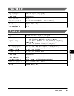
Page 342: ...20 Ib bond 64g m2 to 80g m2 Plain Recycled Color Tracing paper Stack bypass 17 Ib bond to 32 Ib bond 64g m2 to 128g m2 Plain Heavy Recycled Color Letterhead Tracing paper Transparency Labels 3 Holes...

Page 343: ...16cpm 16cpm 16cpm LTRR 11 x 17 129 16cpm 16cpm 16cpm STMTR 11 x 17 200 16cpm 16cpm 16cpm Except when paper is fed from the stack bypass Magnification Direct 1 1 0 7 Reduction 1 0 789 LGL LTR 1 0 733...

Page 344: ...sumption 25W Dimensions H x W x D 4 7 8 x 22 1 4 x 21 1 4 122mm x 565mm x 538mm Weight Approx 18 7 lb 8 5kg Paper feeding system 500 sheets x 2 cassette 20 Ib bond 80g m2 Power source From main unit P...

Page 345: ...ay Non collate Collate Group mode LTR LTRR STMT STMTR 300 sheets 1 7 8 47mm LGL 200 sheets 1 1 4 31mm 11 x 17 150 sheets 1 24mm Staple mode 11 x 17 LTR LTRR LGL 30 sets 1 7 8 47mm Max stapling capacit...

Page 346: ...LGL 25 sheets Saddle Stitch 2 to 10 sheets Available staple size 11 x 17 LGL LTR LTRR Available saddle stitch size 11 x 17 LTRR Available offset size 11 x 17 LGL LTR LTRR STMT Saddle stitcher folding...

Page 347: ...8 170mm x 90mm x 560mm Weight Approx 5 3 lb 2 4kg Capacity 250 sheets LTR 100 sheets Others Power source From main unit Power consumption 35W Dimensions H x W x D 10 x 5 7 8 x 16 1 2 254mm x 149mm x...

Page 348: ...netic type card Optical type card Card readout method Magnetic Optical readout Magnetic card reading direction Inserting Direction Store replay Replay Power source From main unit Dimensions H x W x D...

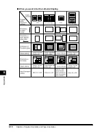
Page 349: ...h logos etc printed beforehand IMPORTANT When the Finisher J1 is attached only the Corner Top Left stapling setting is available NOTE When copying on the rear side of printed paper set the paper in th...

Page 350: ...8 Relation of Original Orientation and Paper Orientation 8 10 Appendix When you want to Set the Left side Stapling...

Page 351: ...Breaker 1 19 C Card Reader C1 Control Card 7 3 7 80 Cassette Feeding Unit W1 7 3 7 4 Cassette U1 5 25 Cassette V1 5 26 Change Auto Clear Time 3 35 Change Auto Sleep Time 3 34 Checking the Breaker 6 3...

Page 352: ...when paper has run out 1 15 Display when selecting paper 1 15 Drawer Eligibility For APS ADS 3 13 Drawers 7 4 Duplexing unit 1 19 E Energy Consumption in Sleep Mode 3 18 Entering Characters 1 32 Envel...

Page 353: ...itial Function 3 8 Initialize Common Settings 3 30 Inner 2way Tray A1 7 3 7 73 Inner tray 7 73 Interrupt key 1 21 L Language Switch 3 28 Left guide 7 15 Lower right cover 7 4 LTRR STMT Original Select...

Page 354: ...2 1 18 Paper drawer 3 4 1 18 Paper Jams 6 2 Paper Stock 5 23 Paper Supply indicator 1 15 7 9 Paper Supply Indicator Function 1 15 Password 1 37 Platen glass 1 19 1 40 Platen glass cover 1 18 Printing...

Page 355: ...47 Standard Stack Bypass Settings 3 24 Staple Mode 7 48 Staple Offset to ON OFF 3 42 Start key 1 20 static charge eliminator 6 23 static charge eliminator cleaning brush 6 24 Stop 2 9 Stop key 1 20 S...

Page 356: ...8 Index 8 16 Appendix Tray Designation 3 21 U Upper cover 7 47 Upper front cover 7 47 Usage Guide 1 12 W Width guide 7 15 Z Zoom Fine Adjustment 3 39...

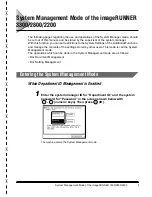
Page 357: ...tem Settings of the Additional Functions and manage the contents of the settings stored by other users This mode is call the System Management mode The operations which can be done in the System Manag...

Page 358: ...ess Additional Functions 2 Press System Settings 3 Enter the System Manager ID Password with numeric keys and press ID The machine enters the System Management mode NOTE Enter the number stored under...

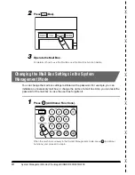
Page 359: ...Auto Clear has taken place returning to the screen specified to display after Auto Clear Managing Mail Box in the System Management Mode You can operate the mail box documents stored by other users Fo...

Page 360: ...e System Management Mode You can change the mail box settings restricted with a password For example you can initialize an unnecessary mail box or change the name of a mail box Also you can reset the...

Page 361: ...the System Password for Password with numeric keys and press ID 2 Press System Settings 3 Enter the System Manager ID Password using numeric keys and press ID The machine enters the System Management...

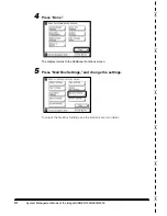
Page 362: ...e of the imageRUNNER 3300 2800 2200 VI 4 Press Done The display returns to the Additional Functions screen 5 Press Mail Box Settings and change the settings To specify the Mail Box Settings see the Ma...

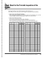
Page 363: ...ace near the machine How to Inspect the Breaker Periodically Follow the procedure described in the Periodic Inspection of the Breaker on p xxv of the image RUNNER 3300 2800 2200 Reference Guide once o...

Page 364: ......

Page 365: ......

Page 366: ...oumer 92414 Courbevoie Cedex France CANON U K LTD Woodhatch Reigate Surrey RH2 8BF United Kingdom CANON DEUTSCHLAND GmbH Europark Fichtenhain A10 47807 Krefeld Germany CANON ITALIA S p A Palazzo L Str...

Reviews: