10. If you replaced the HDD with a new HDD, install system software (see
“Installing System Software” on page 46
).
11. Verify the functionality of the
imagePRESS Server
“To reinstall and verify the imagePRESS Server” on page
).
Restoring imagePRESS Server functionality after service
Complete your inspection and service by reinstalling and verifying the
imagePRESS Server
.
■ To reinstall and verify the imagePRESS Server
1. Reseat all boards, cables, connectors, and other parts loosened or removed during service. When routing cables
in the
imagePRESS Server
make sure that:
• Covers are securely installed after routing cables.
• Cables are not looped around circuit boards or components (such as capacitors and resistors).
• Cable routing does not interfere with the operation of internal components.
• Cables do not lie on or against any internal heating element.
• Cables do not interfere with removing or replacing components.
• Cables do not interfere with opening or closing
imagePRESS Server
panels.
• Cables are not tangled.
• Cable slack is secured with a tie-wrap.
IMPORTANT:
Improper connection of the internal power cables can damage the
imagePRESS Server
.
internal connections” on page 19
“To reinstall and verify the imagePRESS Server” on page 43
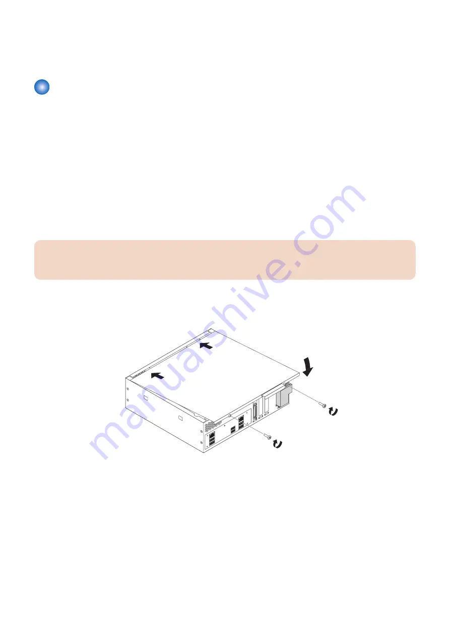
2. Replace the cover on the
imagePRESS Server
.
Make sure that all cables are fully inside the chassis before you replace the cover. Slide the cover until it engages the edge
of the chassis opposite the connector panel, and then lower the cover.
Figure 29: Replacing the chassis cover
3. Replace the two screws that you removed earlier.
Tighten the screws to secure the cover to the
imagePRESS Server
.
4. Reinstall the
imagePRESS Server
on the side of the printer.
For detailed information about removing/installing the printer, see the installation instructions that accompany the printer (not
included in this service guide).
5. Connect the external cables that you removed during inspection or service. Be sure to properly connect the
following cables ( see
“imagePRESS Server connector panel and LED diagnostic codest” on page 17
• Network cable
• Crossover Ethernet cable between the
imagePRESS Server
and printer
• Printer interface cable
•
imagePRESS Server
power cable
3. REPLACING PARTS
43
Summary of Contents for imagePRESS Server M10
Page 7: ...Introduction 1 Introduction 2 Specifications 7 ...
Page 16: ...USING THE IMAGEPRESS SERVER 2 Using the imagePRESS Server 11 ...
Page 20: ...REPLACING PARTS 3 Replacing Parts 15 ...
Page 51: ...INSTALLING SYSTEM SOFTWARE 4 Installing System Software 46 ...
Page 73: ...TROUBLESHOOTI NG 5 Troubleshooting 68 ...
Page 89: ...Installation Procedure Installing the Open I F PCB 1 3x 2 1x 1x 6 INSTALLATION PROCEDURE 83 ...
Page 93: ...11 Installing the imagePRESS Server 1 1x 2 4x 8x 6 INSTALLATION PROCEDURE 87 ...


