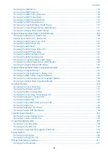
Removing the DADF Motor................................................................................................................ 103
Removing the DADF Solenoid............................................................................................................105
Removing the DADF Pickup Roller Unit.............................................................................................. 106
Removing the DADF Pickup Roller .................................................................................................... 109
Removing the DADF Separation Roller .............................................................................................. 110
Removing the DADF Separation Pad..................................................................................................112
Removing the Copyboard Glass (DADF Model)...................................................................................115
Removing the Contact Image Sensor (DADF Model)........................................................................... 117
Removing the Reader Motor (DADF Model)........................................................................................ 122
Removing the SADF Unit + Reader Unit............................................................................................. 126
Separating the SADF Unit + Reader Unit............................................................................................ 129
Removing the SADF Upper Cover Unit............................................................................................... 131
Removing the SADF Pickup Unit........................................................................................................ 134
Removing the SADF Motor................................................................................................................ 135
Removing the SADF Pickup Roller Unit.............................................................................................. 137
Removing the SADF Pickup Roller .................................................................................................... 140
Removing the SADF Separation Roller .............................................................................................. 141
Removing the SADF Separation Pad..................................................................................................143
Removing the Copyboard Glass (SADF Model)...................................................................................146
Removing the Contact Image Sensor (SADF Model)............................................................................148
Removing the Reader Motor(SADF Model)......................................................................................... 153
Removing the Copyboard Cover.........................................................................................................157
Removing the Copyboard Cover + Reader Unit................................................................................... 157
Removing the Platen Glass (Copyboard Model).................................................................................. 161
Removing the Contact Image Sensor (Copyboard Model).................................................................... 163
Removing the Reader Motor (Copyboard Model).................................................................................168
Removing the Control Panel Unit .......................................................................................................172
Removing the Wireless Lan PCB .......................................................................................................173
Removing the Main Controller PCB ................................................................................................... 173
Removing the Low-Voltage Power Supply Unit....................................................................................176
Removing the Engine Controller PCB ................................................................................................ 181
Removing the Motor PCB ................................................................................................................. 184
Removing the Environment/Pickup Sensor PCB .................................................................................185
Removing the Main Fan.....................................................................................................................187
Removing the Speaker (Fax Model)....................................................................................................188
Removing the NCU PCB (Fax Model)................................................................................................. 190
Removing the Laser Scanner Cover................................................................................................... 192
Removing the Laser Scanner Unit...................................................................................................... 194
Removing the Transfer Roller.............................................................................................................196
Removing the Transfer Unit............................................................................................................... 197
Removing the Developer Disengagement Solenoid............................................................................. 202
Removing the Fixing Unit................................................................................................................... 204
Removing the Fixing Film Unit ...........................................................................................................207
Contents
iii
Summary of Contents for imageCLASS MF264dw
Page 13: ...Product Overview 1 Product Lineup 6 Features 8 Specifications 9 Parts Name 14 ...
Page 67: ...Consumable Parts Consumable parts are not required in this machine 3 Periodical Service 59 ...
Page 68: ...Periodical Service No periodic services are required to this machine 3 Periodical Service 60 ...
Page 89: ...3 80 mm 80 mm 4 Parts Replacement and Cleaning 81 ...
Page 92: ... If the Fax is not installed 3x 2x 1x 2 60 mm 3 4 Parts Replacement and Cleaning 84 ...
Page 96: ...3 4 Parts Replacement and Cleaning 88 ...
Page 97: ...4 5 4 Parts Replacement and Cleaning 89 ...
Page 105: ...2 3 1x 4 Parts Replacement and Cleaning 97 ...
Page 110: ...5 6 4x 1x 1x 7 4 Parts Replacement and Cleaning 102 ...
Page 115: ...3 4 5 4 Parts Replacement and Cleaning 107 ...
Page 116: ...6 4 Parts Replacement and Cleaning 108 ...
Page 122: ...2 3 4 4 Parts Replacement and Cleaning 114 ...
Page 124: ...1 2 2x 3 4 4 Parts Replacement and Cleaning 116 ...
Page 127: ...2 3 4 2x 1x 5 4 Parts Replacement and Cleaning 119 ...
Page 129: ...3 4 2x 1x 5 6 4 Parts Replacement and Cleaning 121 ...
Page 132: ...5 2x 4 Parts Replacement and Cleaning 124 ...
Page 138: ...2 1x 3 1x 4 4 Parts Replacement and Cleaning 130 ...
Page 140: ... Procedure 1 2 4 Parts Replacement and Cleaning 132 ...
Page 144: ... Procedure 1 2 3 2x 4 Parts Replacement and Cleaning 136 ...
Page 146: ...3 4 4 Parts Replacement and Cleaning 138 ...
Page 147: ...5 4 Parts Replacement and Cleaning 139 ...
Page 153: ...1 2 3 4 4 Parts Replacement and Cleaning 145 ...
Page 155: ...1 2 2x 3 4 4 Parts Replacement and Cleaning 147 ...
Page 158: ...2 3 4 2x 1x 5 4 Parts Replacement and Cleaning 150 ...
Page 160: ...3 4 2x 1x 5 6 4 Parts Replacement and Cleaning 152 ...
Page 163: ...5 2x 4 Parts Replacement and Cleaning 155 ...
Page 166: ...2 2x 1x 1x 3 1x 1x 4 Parts Replacement and Cleaning 158 ...
Page 170: ...2 2x 3 4 2x 4 Parts Replacement and Cleaning 162 ...
Page 173: ...2 3 4 2x 1x 5 4 Parts Replacement and Cleaning 165 ...
Page 175: ...3 4 2x 1x 5 6 4 Parts Replacement and Cleaning 167 ...
Page 178: ...5 2x 4 Parts Replacement and Cleaning 170 ...
Page 183: ...2 4x 4 Parts Replacement and Cleaning 175 ...
Page 188: ... If the Fax is not installed 6 2x 1x 7 3x 8 2x 1x 4 Parts Replacement and Cleaning 180 ...
Page 191: ...4 1x 5 1x 6 3x 4 Parts Replacement and Cleaning 183 ...
Page 199: ... Procedure 1 3x 2x 4 Parts Replacement and Cleaning 191 ...
Page 201: ... If the Fax is not installed 2 4x 3 4 Parts Replacement and Cleaning 193 ...
Page 208: ...4 4 Parts Replacement and Cleaning 200 ...
Page 211: ...3 2x 4 1x 4 Parts Replacement and Cleaning 203 ...
Page 213: ...2 3 4x 4 4 Parts Replacement and Cleaning 205 ...
Page 217: ...3 1x 1x 4 5 2x 6 4 Parts Replacement and Cleaning 209 ...
Page 218: ...7 8 9 4 Parts Replacement and Cleaning 210 ...
Page 223: ...4 4 Parts Replacement and Cleaning 215 ...
Page 228: ...Adjustment 5 Adjustment at Parts Replacement 221 ...
Page 230: ...Troubleshooting 6 Test Print 223 Troubleshooting Items 226 Debug Log 228 Version Upgrade 231 ...
Page 242: ...Error Jam Alarm 7 Overview 235 Error Code 238 Jam Code 241 Alarm Code 243 ...
Page 251: ...Alarm Code This machine does not have any Alarm Code 7 Error Jam Alarm 243 ...
Page 287: ...APPENDICES Service Tools 280 General Circuit Diagram 281 Backup Data 283 ...

