


Chapter 4
4-4
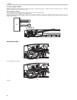
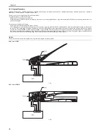
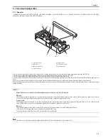
4.1.3 Original Detection
0020-2676
i-SENSYS MF4300dn / i-SENSYS MF4350d / i-SENSYS MF4380dn / i-SENSYS MF4310/4318 / i-SENSYS MF4320d / i-SENSYS MF4330d / i-SENSYS
MF4340d / i-SENSYS D450d / i-SENSYS MF4370dn
There are two types of original detection in this equipment.
1. Original Presence / Absence Detection
Detected by DS (Document Sensor: PS106)
Setting the original onto the original tray pushes up the actuator, activating (light shielded =>light transmitted) the DS (PS106), and resulting in detection of the
presence of original.
2. Detection of the End of the Original
Detected by the DES (Document End Sensor: PS105)
The leading edge of the original that is fed pushes up the actuator, activating the DES (PS105) (light shielded =>light transmitted) and resulting in detection of
the reach of the leading edge of original. Furthermore, when the trailing edge of the original passes the actuator position, the actuator returns to the original
position, inactivating the DES (PS105) (light transmitted => light shielded). The trailing edge of the original is detected by this mechanism. The original length
that can be scanned with this equipment is less than 400 mm. Passing of the original longer than this results in jam stop. The original length is calculated by the
time it takes from detection of the leading edge of the original to detection of the trailing edge of the original.
MEMO:
There is no function to detect the original size (original width, length) in this equipment.
In the case of ADF
F-4-7
In the case of DADF
F-4-8
Summary of Contents for i-SENSYS MF4300dn
Page 1: ...Aug 22 2008 Service Manual MF4300 Series ...
Page 2: ......
Page 6: ......
Page 12: ...Contents 15 1 1 Solvents Lubricants Table 15 1 ...
Page 13: ...Chapter 1 Introduction ...
Page 14: ......
Page 16: ......
Page 32: ......
Page 33: ...Chapter 2 Basic Operation ...
Page 34: ......
Page 36: ......
Page 38: ......
Page 39: ...Chapter 3 Original Exposure System ...
Page 40: ......
Page 42: ......
Page 44: ...Chapter 3 3 2 F 3 1 ...
Page 49: ...Chapter 4 Original Feeding System ...
Page 50: ......
Page 52: ......
Page 55: ...Chapter 4 4 3 F 4 6 ...
Page 66: ......
Page 67: ...Chapter 5 Laser Exposure ...
Page 68: ......
Page 70: ......
Page 73: ...Chapter 5 5 3 ...
Page 76: ......
Page 77: ...Chapter 6 Image Formation ...
Page 78: ......
Page 80: ......
Page 85: ...Chapter 7 Pickup and Feed System ...
Page 86: ......
Page 88: ......
Page 96: ......
Page 97: ...Chapter 8 Fixing System ...
Page 98: ......
Page 100: ......
Page 108: ......
Page 109: ...Chapter 9 External and Controls ...
Page 110: ......
Page 112: ......
Page 121: ...Chapter 10 Maintenance and Inspection ...
Page 122: ......
Page 124: ......
Page 128: ......
Page 129: ...Chapter 11 Measurement and Adjustments ...
Page 130: ......
Page 132: ......
Page 135: ...Chapter 12 Correcting Faulty Images ...
Page 136: ......
Page 138: ......
Page 144: ...Chapter 12 12 6 2 DCNT PCB 3 Power supply PCB 4 High voltage PCB SW301 Interlock switch ...
Page 145: ...Chapter 13 Error Code ...
Page 146: ......
Page 147: ...Contents Contents 13 1 Error Code 13 1 13 1 1 Error Code Outline 13 1 13 1 2 Error Code 13 1 ...
Page 148: ......
Page 153: ...Chapter 14 Service Mode ...
Page 154: ......
Page 156: ...Contents 14 3 2 3 Sensor test 14 16 14 3 2 4 Key test 14 16 ...
Page 174: ......
Page 175: ...Chapter 15 Service Tools ...
Page 176: ......
Page 177: ...Contents Contents 15 1 Service Tools 15 1 15 1 1 Solvents Lubricants Table 15 1 ...
Page 178: ......
Page 180: ......
Page 181: ...Aug 22 2008 ...
Page 182: ......


