


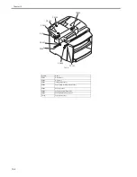


Chapter 13
13-3
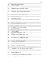
0069
Capability no match paper size after received is DCS signal.
0070
User press stop key within receiving.
0071
Memory full within receiving.
0080
Can't detect any G3 signal within 35 sec. specified by ITU-T in phase B.
0081
Received DTC signal in transmission phase.
0082
Transmitting unit receives a signal other than DIS or DTC. And DCN in phase B.
0083
Detected FSK signal, but Can't receive any signal within 35 sec.
0084
Detect DCN signal in phase B.
0085
Transmitting unit sending DCS 3 times consecutively, but each time responds with DIS/DTC
0086
Detected responds signal other than DTC,DIS,FTT,DCN or CFR after sending DCS.
0087
Training attempt has failed because speed unit can't adjust to low lower speed.
0088
Received DCN signal after sending out DCS signal
008B
Receivers protcol of DIS is received, but it is not compatible with our machine.
008C
Remote side or our side not support capability.
008D
Receivers protocol of DIS is received, but remote side can't receive document temporary, may because by run out of paper or other reason.
008F
Modem not ready to received V.34 data within 6 sec after received CFR signal.
0090
Called side document not ready for our polling.
0091
Can't receive any commabd after send DCN signal 3 times consecutively
0093
Received DCN signal after sending out DCN signal
0094
Time out during transmit ECM frame or RCP command.
0095
Wrong ID number
0096
SUBADDRESS/PASSWORD capability not match in polling Rx mode.
009A
Can't detect any signal after sending CI signal.
009D
Remote side hang up before V.34 modem enter phase 2 state in V.34 polling Rx.
009E
Manual Tx over 15 minutes whin in phase C by non-ECM mode.
00A0
User stop or cancel transmission job.
00A1
Document JAM within transmission
00AE
Can't finished V.8 procedure or detect V.21 signal after CM signal
00AF
Modem can't enter into control channel after TX side sending out RCP signal
for V34
00B1
Can't finish V.8 procedure or detect V.21 signal after ANSam signal within 35 sec.
00B2
Can't detect phase 2 signal after our side sending CJ signal within 30 sec
00B3
Can't detect correct V.21 or JM signal after sending CM or CJ signal.
00B4
Can't detect correct phase 2 signal within 25 second after CM/JM signal exchange.
00B5
Can't detect phase 3 signal after Phase 2
00B6
Can't detect phase 4 signal within 25 sec after CM/JM exchange.
00B8
Remote side disconnect after our side sending DCS signal in V.34.
00BA
Cannot received correct signal after our side sending DTC signal in V.34.
00BB
Every time our side received DIS signal after sending DTC in V.34.
00BC
Modem can't ready within 10 second after entering primary channel in V.34.
00BD
Can't detect correct V.21 or JM signal after detected FSK frequency.
00BE
Remote side no document to be polled after V.8 handshaking.
00BF
Capability no match after V.8 handshaking
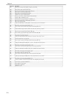
00C1
At phase-D, transmitting units out EOP 3 times consecutively, but receive no answer from receiving unit.
00C2
Remote side disconnect after sending out V.8 CM signal.
00C4
After sending MPS signal, the received is not one of MCF, RTN, PIP, PIN, RTP, DCN.
00C5
Received DCN signal after sending MPS signal.
00C9
At phase D, sending MPS 3 times consecutively, but no answer from receiveing unit.
00CA
After sending EOP signal, the received is not one of MCF, RTN, PIP, PIN, PRI-EOP, DCN, RTP.
00CB
After sending EOP signal, the received is DCN signal.
Error Code
Description
Summary of Contents for i-SENSYS MF4300dn
Page 1: ...Aug 22 2008 Service Manual MF4300 Series ...
Page 2: ......
Page 6: ......
Page 12: ...Contents 15 1 1 Solvents Lubricants Table 15 1 ...
Page 13: ...Chapter 1 Introduction ...
Page 14: ......
Page 16: ......
Page 32: ......
Page 33: ...Chapter 2 Basic Operation ...
Page 34: ......
Page 36: ......
Page 38: ......
Page 39: ...Chapter 3 Original Exposure System ...
Page 40: ......
Page 42: ......
Page 44: ...Chapter 3 3 2 F 3 1 ...
Page 49: ...Chapter 4 Original Feeding System ...
Page 50: ......
Page 52: ......
Page 55: ...Chapter 4 4 3 F 4 6 ...
Page 66: ......
Page 67: ...Chapter 5 Laser Exposure ...
Page 68: ......
Page 70: ......
Page 73: ...Chapter 5 5 3 ...
Page 76: ......
Page 77: ...Chapter 6 Image Formation ...
Page 78: ......
Page 80: ......
Page 85: ...Chapter 7 Pickup and Feed System ...
Page 86: ......
Page 88: ......
Page 96: ......
Page 97: ...Chapter 8 Fixing System ...
Page 98: ......
Page 100: ......
Page 108: ......
Page 109: ...Chapter 9 External and Controls ...
Page 110: ......
Page 112: ......
Page 121: ...Chapter 10 Maintenance and Inspection ...
Page 122: ......
Page 124: ......
Page 128: ......
Page 129: ...Chapter 11 Measurement and Adjustments ...
Page 130: ......
Page 132: ......
Page 135: ...Chapter 12 Correcting Faulty Images ...
Page 136: ......
Page 138: ......
Page 144: ...Chapter 12 12 6 2 DCNT PCB 3 Power supply PCB 4 High voltage PCB SW301 Interlock switch ...
Page 145: ...Chapter 13 Error Code ...
Page 146: ......
Page 147: ...Contents Contents 13 1 Error Code 13 1 13 1 1 Error Code Outline 13 1 13 1 2 Error Code 13 1 ...
Page 148: ......
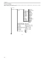
Page 153: ...Chapter 14 Service Mode ...
Page 154: ......
Page 156: ...Contents 14 3 2 3 Sensor test 14 16 14 3 2 4 Key test 14 16 ...
Page 174: ......
Page 175: ...Chapter 15 Service Tools ...
Page 176: ......
Page 177: ...Contents Contents 15 1 Service Tools 15 1 15 1 1 Solvents Lubricants Table 15 1 ...
Page 178: ......
Page 180: ......
Page 181: ...Aug 22 2008 ...
Page 182: ......


