


Chapter 14
14-4
F-14-4
F-14-5
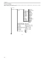
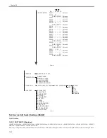
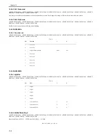
14.2 Service Soft Switch Settings (SSSW)
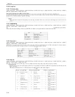
14.2.1 Outline
14.2.1.1 SOFT SWITCH Explained
0020-2762
i-SENSYS MF4300dn / i-SENSYS MF4350d / i-SENSYS MF4380dn / i-SENSYS MF4310/4318 / i-SENSYS MF4320d / i-SENSYS MF4330d / i-SENSYS
MF4340d / i-SENSYS D450d / i-SENSYS MF4370dn
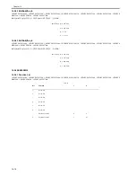
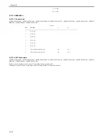
Each entry / setting item of SOFT SWITCH consists of 8 bitswitches. Each bitswitch displayed on the screen has an assigned number as shown in the figure below.
SOFT SWITCH
Bit
Not used
Not used
Not used
Not used
Not used
Not used
Not used
Not used
Not used
Not used
Not used
Not used
Not used
Not used
Not used
Not used
Not used
Not used
Not used
Not used
1 2 3 4 5 6 7 8
SW01
SW02
SW07
SW08
SW09
SW10
SW16
SW17
SW18
SW19
SW20
SW21
SW22
SW23
SW24
SW30
SW37
SW51
SW52
SW53
SW54
- - - - - - - -
- 0 0 - - - - -
- - - - - - - -
- - - - - - - -
- - - - - - - -
1 0 - - - - - -
- - 0 - - - - -
- - - - - - - -
- - - - - - - -
- - - - - - - -
- - - - - - - -
- - - - - - - -
- - - - - - - -
- - - - - - - -
- - - - - - - -
- - - - - - 1 0
- - - 0 0 0 - -
- - 0 0 - - - -
- - - - - - - -
- - - - - - - -
- - - - - 0 1 0
SW55
SW64:
SW03
SW06:
SW11
SW15:
SW25
SW29:
SW31
SW36:
SW38
SW50:
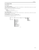
CLEAR DATA
DRAM CLEAR
MEMORY CLEAR
PRINT COUNTER
SCAN COUNTER
PASSWORD CLEAR
H/W TEST
SIGNAL TEST
RELAY TEST
SENSOR TEST
DIAL TEST
VOLUME TEST
KEY TEST
AGING
CIS TEST
BOOK SCAN TEST
COPY TEST
JPN PSUDO RING
ADF SCAN TEST
IR SCAN TEST
FUNCTION
PRINT TEST PATTERN
CONT. PRINTING
BLACK
E
FIX
ASF
WHITE
SQUARE
ON
OFF
REPORT
SERVICE DATA LIST
Summary of Contents for i-SENSYS MF4300dn
Page 1: ...Aug 22 2008 Service Manual MF4300 Series ...
Page 2: ......
Page 6: ......
Page 12: ...Contents 15 1 1 Solvents Lubricants Table 15 1 ...
Page 13: ...Chapter 1 Introduction ...
Page 14: ......
Page 16: ......
Page 32: ......
Page 33: ...Chapter 2 Basic Operation ...
Page 34: ......
Page 36: ......
Page 38: ......
Page 39: ...Chapter 3 Original Exposure System ...
Page 40: ......
Page 42: ......
Page 44: ...Chapter 3 3 2 F 3 1 ...
Page 49: ...Chapter 4 Original Feeding System ...
Page 50: ......
Page 52: ......
Page 55: ...Chapter 4 4 3 F 4 6 ...
Page 66: ......
Page 67: ...Chapter 5 Laser Exposure ...
Page 68: ......
Page 70: ......
Page 73: ...Chapter 5 5 3 ...
Page 76: ......
Page 77: ...Chapter 6 Image Formation ...
Page 78: ......
Page 80: ......
Page 85: ...Chapter 7 Pickup and Feed System ...
Page 86: ......
Page 88: ......
Page 96: ......
Page 97: ...Chapter 8 Fixing System ...
Page 98: ......
Page 100: ......
Page 108: ......
Page 109: ...Chapter 9 External and Controls ...
Page 110: ......
Page 112: ......
Page 121: ...Chapter 10 Maintenance and Inspection ...
Page 122: ......
Page 124: ......
Page 128: ......
Page 129: ...Chapter 11 Measurement and Adjustments ...
Page 130: ......
Page 132: ......
Page 135: ...Chapter 12 Correcting Faulty Images ...
Page 136: ......
Page 138: ......
Page 144: ...Chapter 12 12 6 2 DCNT PCB 3 Power supply PCB 4 High voltage PCB SW301 Interlock switch ...
Page 145: ...Chapter 13 Error Code ...
Page 146: ......
Page 147: ...Contents Contents 13 1 Error Code 13 1 13 1 1 Error Code Outline 13 1 13 1 2 Error Code 13 1 ...
Page 148: ......
Page 153: ...Chapter 14 Service Mode ...
Page 154: ......
Page 156: ...Contents 14 3 2 3 Sensor test 14 16 14 3 2 4 Key test 14 16 ...
Page 174: ......
Page 175: ...Chapter 15 Service Tools ...
Page 176: ......
Page 177: ...Contents Contents 15 1 Service Tools 15 1 15 1 1 Solvents Lubricants Table 15 1 ...
Page 178: ......
Page 180: ......
Page 181: ...Aug 22 2008 ...
Page 182: ......


