


Chapter 3
3-5
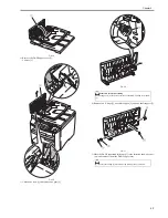
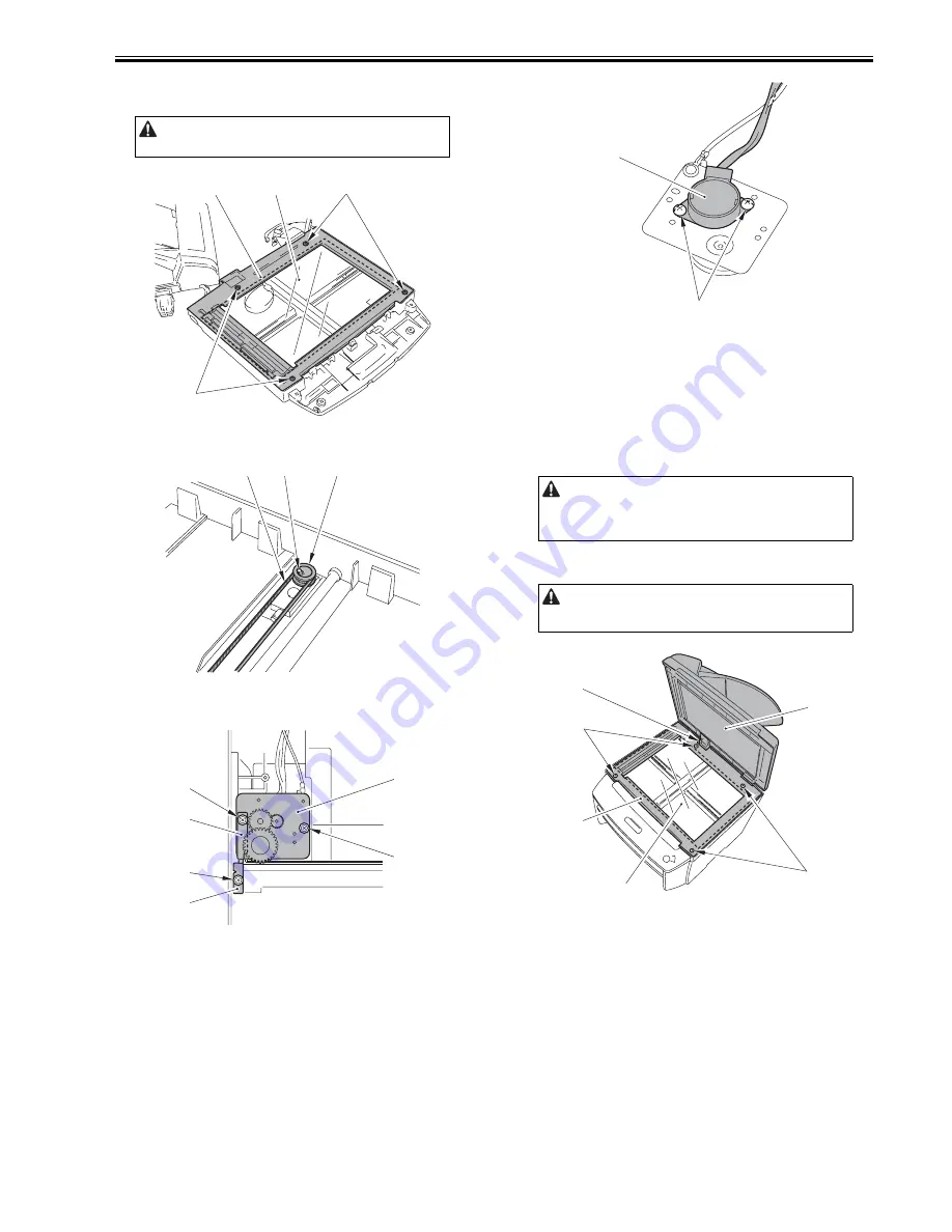
6) Remove the flat cable [2] to remove the control panel unit [3].
7) Remove the 4 screws [1], and detach the copyboard cover [2].
8) Remove the copyboard glass [3].
F-3-13
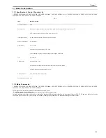
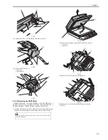
9) Remove the claw [1] to remove the gear [3] together with the belt [2].
F-3-14
10) Remove the 3 screws [1] to remove the shaft retainer [2], the grounding
plate [3] and the motor unit [4].
F-3-15
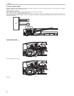
11) Remove the 2 screws [1] to remove the flat bed motor [2].
F-3-16
3.2.3 Contact Sensor
3.2.3.1 Removing the Contact Sensor
0020-2673
i-SENSYS MF4300dn / i-SENSYS MF4350d / i-SENSYS MF4380dn / i-
SENSYS MF4310/4318 / i-SENSYS MF4320d / i-SENSYS MF4330d / i-
SENSYS MF4340d / i-SENSYS D450d / i-SENSYS MF4370dn
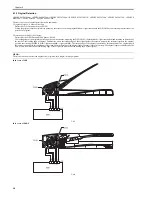
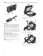
1) Open the copyboard cover unit [1] to remove in the direction of the arrow.
Pull out the hinge [2] on the left side while tilting it toward the rear side.
2) Remove the 4 screws [3], and detach the copyboard glass cover [4].
3) Remove the copyboard glass cover [5].
F-3-17
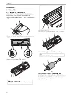
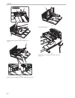
4) Remove the 2 spacers [1].
5) Remove the contact sensor unit [2] upward.
Do not make dirty the bottom of the copyboard glass.
[2]
[3]
[1]
[1]
[1]
[2]
[3]
[1]
[1]
[4]
[3]
[1]
[2]
For the removed copyboard cover unit, be sure to place it above a table so
that the cable is not damaged.
Be sure not to get the bottom surface of the scanner glass soiled.
[1]
[2]
[1]
[4]
[5]
[2]
[3]
[3]
Summary of Contents for i-SENSYS MF4300dn
Page 1: ...Aug 22 2008 Service Manual MF4300 Series ...
Page 2: ......
Page 6: ......
Page 12: ...Contents 15 1 1 Solvents Lubricants Table 15 1 ...
Page 13: ...Chapter 1 Introduction ...
Page 14: ......
Page 16: ......
Page 32: ......
Page 33: ...Chapter 2 Basic Operation ...
Page 34: ......
Page 36: ......
Page 38: ......
Page 39: ...Chapter 3 Original Exposure System ...
Page 40: ......
Page 42: ......
Page 44: ...Chapter 3 3 2 F 3 1 ...
Page 49: ...Chapter 4 Original Feeding System ...
Page 50: ......
Page 52: ......
Page 55: ...Chapter 4 4 3 F 4 6 ...
Page 66: ......
Page 67: ...Chapter 5 Laser Exposure ...
Page 68: ......
Page 70: ......
Page 73: ...Chapter 5 5 3 ...
Page 76: ......
Page 77: ...Chapter 6 Image Formation ...
Page 78: ......
Page 80: ......
Page 85: ...Chapter 7 Pickup and Feed System ...
Page 86: ......
Page 88: ......
Page 96: ......
Page 97: ...Chapter 8 Fixing System ...
Page 98: ......
Page 100: ......
Page 108: ......
Page 109: ...Chapter 9 External and Controls ...
Page 110: ......
Page 112: ......
Page 121: ...Chapter 10 Maintenance and Inspection ...
Page 122: ......
Page 124: ......
Page 128: ......
Page 129: ...Chapter 11 Measurement and Adjustments ...
Page 130: ......
Page 132: ......
Page 135: ...Chapter 12 Correcting Faulty Images ...
Page 136: ......
Page 138: ......
Page 144: ...Chapter 12 12 6 2 DCNT PCB 3 Power supply PCB 4 High voltage PCB SW301 Interlock switch ...
Page 145: ...Chapter 13 Error Code ...
Page 146: ......
Page 147: ...Contents Contents 13 1 Error Code 13 1 13 1 1 Error Code Outline 13 1 13 1 2 Error Code 13 1 ...
Page 148: ......
Page 153: ...Chapter 14 Service Mode ...
Page 154: ......
Page 156: ...Contents 14 3 2 3 Sensor test 14 16 14 3 2 4 Key test 14 16 ...
Page 174: ......
Page 175: ...Chapter 15 Service Tools ...
Page 176: ......
Page 177: ...Contents Contents 15 1 Service Tools 15 1 15 1 1 Solvents Lubricants Table 15 1 ...
Page 178: ......
Page 180: ......
Page 181: ...Aug 22 2008 ...
Page 182: ......


