CHAPTER 3 MECHANICAL SYSTEM
3-8
COPYRIGHT © 1998 CANON INC. CANON DADF-A1 REV.0 DEC. 1998 PRINTED IN JAPAN (IMPRIME AU JAPON)
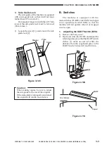
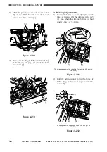
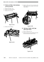
6) Mark the position of the belt motor count
[5] on the DADF with a scriber, and
remove the three screws [6].
[6]
[5]
Figure 3-209
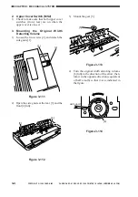
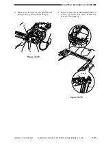
7) Detach the feeding belt drive roller side [8]
of the timing belt [7], and detach the belt
motor unit [5].
[5]
[7]
[8]
Figure 3-210
2. Making Adjustments
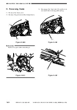
1) Secure the belt motor unit [2] in place with
three screws so that the displacement is 3
±1 mm when the timing belt is pushed
under a force of 3 ±1 mm.
[1]
[3]
[2]
50mm (approx.)
200 20g
+
3
1mm
+
The spring gauge must be capable of measuring 600 g or so
(CK-0058).
Figure 3-211
2) Pull the belt tensioner [4] with a force of
500 ± 50 g, and secure it in place with the
screw [5].
[4]
[5]
500 20g
+
The spring must be capable of measuring 600 g or so
(CK-0058).
Figure 3-212

