CHAPTER 5 TROUBLESHOOTING
5-16
COPYRIGHT © 1998 CANON INC. CANON DADF-A1 REV.0 DEC. 1998 PRINTED IN JAPAN (IMPRIME AU JAPON)
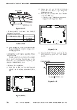
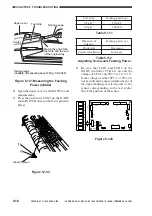
Spring gauge
(capable of measuring about 600 g; CK-0058)
Upper cover
Center
Test strip
Spring gauge
Match the end of the
test strip and the end
of the original tray.
Figure 5-141 Measuring the Feeding
Power (middle)
4) Open the upper cover of the DADF to end
measurement.
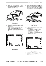
5) Press the push switch SW3 on the DADF
controller PCB once (at the front, glued in
place).
[1]
[2]
Glued in place
Figure 5-142
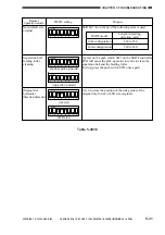
Table 5-111
Feeding power (g)
270±20
300±20
Test strip
64 g/m
2
80 g/m
2
Feeding power (g)
Decreases
Increases
Direction of
rotation
Clockwise
Counterclockwise
Table5-112
Adjusting Screw and Feeding Power
6) Be sure that LED1 and LED2 on the
DADF controller PCB are on and the
voltage of TP2-1 and TP2-2 is 1.1±0.1 V.
If the voltage of either TP2-1 or TP2-2 is
not as indicated, suspect displacement of
the light-emitting/-receiving unit of the
sensor corresponding to the test probe;
check the position of the sensor.
ON
12345678
LED1
LED2
SW1
TP1
J10
J15
J1
CB1
J2
J14
J12
J11
J7
J6
J13
J5
J9
J8
J3
6
1
B12
B1
2
1
1
3
1
2
1
3
1
2
13
1
14
2
A1
A12
1
1
1
1
9
10
1
4
2
2
8
1
7
1
DSW1
SW2
SW3
Figure 5-143


