


Chapter 7
7-5
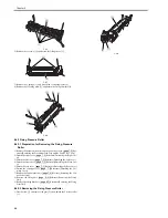
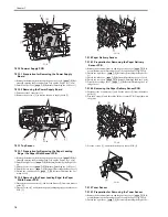
F-7-13
4) Remove the clamp [1] and disconnect the 2 flat cables [2].
5) Free the harness [4] from the guide [3].
6) Remove the screw [5] and turn the DCNT board [6] upside down.
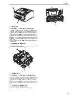
F-7-14
7) Disconnect the 2 connectors [1].
8) Remove the 2 screws [2] to remove the DCNT board [4] from the plate [3].
F-7-15
7.2.11 High-voitage Power Supply PCB
7.2.11.1 Preparation for Removing the High-Voltage
Power Supply Board
0018-4153
1) Remove the document feed tray and the paper tray cover.
(page 7-2)
Ref-
erence[Removing the Document Feed Tray and the Paper Tray Cover]
2) Detach the right cover.
(page 7-2)
Reference[Detaching the Right Cov-
er]
3) Detach the left cover.
(page 7-2)
Reference[Detaching the Left Cover]
4) Detach the rear cover.
(page 7-1)
Reference[Detaching the Rear Cover]
5) Detach the cartridge cover.
(page 7-3)
Reference[Detaching the Car-
tridge Cover]
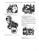
7.2.11.2 Removing the High-Voltage Power Supply Board
0018-4154
1) Disconnect the flat cable [1].
2) Remove the clamp [2].
3) Disconnect the 7 connectors [3].
4) Free the harness [5] from the cable guide [4].
F-7-16
5) Disconnect the terminal [1].
6) Remove the 4 screws [2].
7) Disengage the claw [3] to the direction of the arrow [A] to remove the
high-voltage power supply board [4].
[2]
[1]
[2]
[1] [2] [5]
[6]
[3]
[4]
[3]
[2]
[4]
[1]
[5]
[4]
[3]
[1]
[2]
[3]
Summary of Contents for FaxPhone L90
Page 1: ...Feb 6 2008 Service Manual L90 L140 L160 L230 Series FAX L140 ...
Page 2: ......
Page 6: ......
Page 12: ...Contents ...
Page 13: ...Chapter 1 Introduction ...
Page 14: ......
Page 16: ......
Page 23: ...Chapter 2 Document Feed and Exposure System ...
Page 24: ......
Page 26: ......
Page 33: ...Chapter 3 Laser Exposure ...
Page 34: ......
Page 36: ......
Page 38: ......
Page 39: ...Chapter 4 Image Formation ...
Page 40: ......
Page 42: ......
Page 44: ......
Page 45: ...Chapter 5 Pickup and Feed System ...
Page 46: ......
Page 48: ......
Page 53: ...Chapter 6 Fixing System ...
Page 54: ......
Page 56: ......
Page 61: ...Chapter 7 External and Controls ...
Page 62: ......
Page 72: ......
Page 73: ...Chapter 8 Maintenance and Inspection ...
Page 74: ......
Page 76: ......
Page 80: ......
Page 81: ...Chapter 9 Measurement and Adjustments ...
Page 82: ......
Page 84: ......
Page 87: ...Chapter 10 Correcting Faulty Images ...
Page 88: ......
Page 90: ......
Page 93: ...Chapter 11 Error Code ...
Page 94: ......
Page 95: ...Contents Contents 11 1 Error Code 11 1 11 1 1 Error Code 11 1 ...
Page 96: ......
Page 100: ......
Page 101: ...Chapter 12 Service Mode ...
Page 102: ......
Page 104: ......
Page 121: ...Chapter 13 Service Tools ...
Page 122: ......
Page 123: ...Contents Contents 13 1 Service Tools 13 1 13 1 1 Solvent Oil List 13 1 ...
Page 124: ......
Page 126: ......
Page 127: ...Feb 6 2008 ...
Page 128: ......


