


Chapter 7
7-2
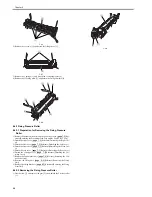
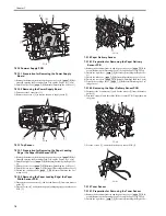
3) Push the left of the rear cover [1] in the arrow [A] direction to disengage
the claw [2] from the receptacle hole [3].
4) Insert a screwdriver etc into the indicated hole [4] by approx 10mm in the
horizontal direction and push the claw in the arrow [B] direction to disen-
gage the claw [5] from the receptacle hole [6].
5) Detach the rear cover [1] in the arrow [C] direction.
F-7-3
6) Free the grounding cable [2] from the cable guide on the rear cover [1].
F-7-4
7.2.3 Right Cover
7.2.3.1 Preparation for Detaching the Right Cover
0018-3819
1) Remove the document feed tray and the paper tray cover.
(page 7-2)
Ref-
erence[Removing the Document Feed Tray and the Paper Tray Cover]
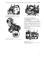
7.2.3.2 Detaching the Right Cover
0018-3820
1) Open the cartridge cover [1] in the direction of the arrow [A].
2) Remove the screw [2].
3) Disengage the 3 claws [3] and open the right cover [4] in the direction of
the arrow [B].
4) Disengage the claw [5] to detach the right cover [4].
F-7-5
7.2.4 Left Cover
7.2.4.1 Preparation for Detaching the Left Cover
0018-3821
1) Remove the document feed tray and the paper tray cover.
(page 7-2)
Ref-
erence[Removing the Document Feed Tray and the Paper Tray Cover]
7.2.4.2 Detaching the Left Cover
0018-3822
1) Open the cartridge cover [1] in the direction of the arrow [A].
2) Remove the 2 screws [2].
3) Disengage the 3 claws [3] and open the left cover [4] in the direction of
the arrow [B].
4) Disengage the claw [5] to detach the left cover [4].
F-7-6
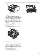
7.2.5 External Cover
7.2.5.1 Removing the Document Feed Tray and the Paper
Tray Cover
0018-3818
1) Remove the document feed tray [1] and paper tray cover [2].
Be sure not to tilt or forcibly insert a screwdriver. Failure to do so may
damage the sensor flag on the paper width sensor (PS802).
Be sure not to forcibly detach the rear cover. Failure to do so may cuts the
grounding wire inside the rear cover.
[3]
[2]
[A]
[B]
[1]
[C]
[6]
[4]
[5]
[1]
[2]
[1]
[A]
[B]
[2]
[3]
[3]
[4]
[5]
[1]
[A]
[B]
[2]
[3]
[4]
[5]
Summary of Contents for FaxPhone L90
Page 1: ...Feb 6 2008 Service Manual L90 L140 L160 L230 Series FAX L140 ...
Page 2: ......
Page 6: ......
Page 12: ...Contents ...
Page 13: ...Chapter 1 Introduction ...
Page 14: ......
Page 16: ......
Page 23: ...Chapter 2 Document Feed and Exposure System ...
Page 24: ......
Page 26: ......
Page 33: ...Chapter 3 Laser Exposure ...
Page 34: ......
Page 36: ......
Page 38: ......
Page 39: ...Chapter 4 Image Formation ...
Page 40: ......
Page 42: ......
Page 44: ......
Page 45: ...Chapter 5 Pickup and Feed System ...
Page 46: ......
Page 48: ......
Page 53: ...Chapter 6 Fixing System ...
Page 54: ......
Page 56: ......
Page 61: ...Chapter 7 External and Controls ...
Page 62: ......
Page 72: ......
Page 73: ...Chapter 8 Maintenance and Inspection ...
Page 74: ......
Page 76: ......
Page 80: ......
Page 81: ...Chapter 9 Measurement and Adjustments ...
Page 82: ......
Page 84: ......
Page 87: ...Chapter 10 Correcting Faulty Images ...
Page 88: ......
Page 90: ......
Page 93: ...Chapter 11 Error Code ...
Page 94: ......
Page 95: ...Contents Contents 11 1 Error Code 11 1 11 1 1 Error Code 11 1 ...
Page 96: ......
Page 100: ......
Page 101: ...Chapter 12 Service Mode ...
Page 102: ......
Page 104: ......
Page 121: ...Chapter 13 Service Tools ...
Page 122: ......
Page 123: ...Contents Contents 13 1 Service Tools 13 1 13 1 1 Solvent Oil List 13 1 ...
Page 124: ......
Page 126: ......
Page 127: ...Feb 6 2008 ...
Page 128: ......


