background image

Chapter 1


1-8

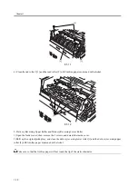
3. No. 1 Registration Roller, No. 2 Registration Roller, No. 1 Registration Roll, No. 2 Registration Roll, and
Reversing Roller.
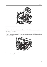
1) Clean the following in the order indicated: platen roller, No. 1 registration roll [1], No. 1 registration roller [2],

No. 2 registration roll [3], No. 2 registration roller [4], reversing roller [5].

1. make the following selections in service mode to highlight [ROLL-CLN], and press the OK key to rotate the

rollers: FEEDER>FUNCTION>ROLL-CLN.

2. force lint-free paper moistened with alcohol against the rollers to clean them.
3. press the OK key to stop the rollers.

Memo:

The No. 1 registration roller and the No. 2 registration roller will not rotate even when the foregoing service mode is
executed (i.e., FEEDER>FUNCTION>ROLL-CLN).

F-1-8

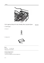
2) Clean the feeder inside cover [1], feed guide [2], reversing guide [3], delivery guide [4], and registration guide [5]
(including sheets) with lint-free paper moistened with alcohol.

[1]

[2]

[3]

[4]

[5]

Summary of Contents for DADF-M1

Page 1: ...Feb 21 2005 Portable Manual Feeder DADF M1 ...

Page 2: ......

Page 3: ... need arises In the event of major changes in the contents of this manual over a long or short period Canon will issue a new edition of this manual The following paragraph does not apply to any countries where such provisions are inconsistent with local law Trademarks The product names and company names used in this manual are the registered trademarks of the individual companies Copyright This ma...

Page 4: ...quiring care to avoid combustion fire Indicates an item prohibiting disassembly to avoid electric shocks or problems Indicates an item requiring disconnection of the power plug from the electric outlet Indicates an item intended to provide notes assisting the understanding of the topic in question Indicates an item of reference assisting the understanding of the topic in question Provides a descri...

Page 5: ...sed to indicate Low The voltage value however differs from circuit to circuit In addition the asterisk as in DRMD indicates that the DRMD signal goes on when 0 In practically all cases the internal mechanisms of a microprocessor cannot be checked in the field Therefore the operations of the microprocessors used in the machines are not discussed they are explained in terms of from sensors to the in...

Page 6: ......

Page 7: ... of opening at 90 deg 2 1 2 1 3Sensor Output 2 1 2 1 4Tray Width 2 2 2 1 5Eliminating the Tilt 2 2 2 1 6Height 2 3 2 1 7Right Angle 2 3 2 1 8Angle Guide angle of opening of 70 deg 2 4 2 1 9Magnification 2 5 2 1 10Horizontal Registration 2 6 2 1 11Leading Edge Registration 2 7 2 1 12White Level 2 8 2 1 13Adjusting the Hinge Pressure 2 8 2 2 Adjustment at Time of Parts Replacement 2 9 2 2 1Overview ...

Page 8: ...l Placement led PCB 4 4 Chapter 5 System Construction 5 1 Basic Construction 5 1 5 1 1Overview of the Electrical Circuitry 5 1 5 1 2Inputs to the ADF Controller PCB 5 1 5 1 3Outputs from the ADF Driver PCB 5 2 5 2 Product Specifications 5 4 5 2 1Specifications 5 4 ...

Page 9: ...Chapter 1 Maintenance and Inspection ...

Page 10: ......

Page 11: ...laced Parts 1 1 1 2 Durables 1 2 1 2 1 Durables 1 2 1 3 Periodical Servicing 1 3 1 3 1 Scheduled Servicing Chart 1 3 1 4 Cleaning 1 6 1 4 1 Parts of the ADF 1 6 1 4 2 Rollers and Guides 1 6 1 4 3 Sensors 1 12 1 4 4 Applying Silicone Oil to the Reading Glass copyboard glass 1 16 ...

Page 12: ......

Page 13: ...Chapter 1 1 1 1 1 Periodically Replaced Parts 1 1 1 Periodically Replaced Parts 0003 1674 The machine does not have parts that must be replaced on a periodical basis ...

Page 14: ...e of a group of evaluation data points Parts Numbers may subject to change because of design No Parts name Parts No Q ty Lifetime 1 Pickup roller FC3 0722 1 80 000 originals 2 Separation Base FL2 0748 1 80 000 originals 3 Feed Roller FC5 3155 1 80 000 originals 4 Separation pad FL2 0749 1 80 000 originals 5 Dust colleting tapeA FC5 2959 1 80 000 originals 6 Dust colleting tapeB FC5 2960 1 80 000 o...

Page 15: ... Parts name Servicing 1 80 000 originals or 6 months 160 000 originals or 12 month 1 White plate copyboard cover A 2 Post separation sensor prism A 3 Read sensor prism A 4 Delivery reversal sensor prism A 5 No 1 registration roller A 6 No 1 registration roll A 7 No 2 registration roller A 8 No 2 registration roll A 9 Read roller 1 A 10 Read roll 1 A 11 Platen roller A 12 Platen upstream roll A 13 ...

Page 16: ... Delivery reversing upper roller A 19 Delivery reversing lower roller A 20 Original pickup tray A 21 Open close guide including sheets A 22 Delivery guide A 23 Reversing guide A 24 Pre registration guide including sheets A 25 Feed guide A 26 Reversing flapper A 27 White plastic film A 28 Dust colleting tape C 29 Reading glass 2 B 30 DADF height See the Adjustment Procedure D 31 Roll scraper A No P...

Page 17: ...F 1 1 F 1 2 F 1 3 2 3 20 16 17 10 9 12 11 13 14 15 19 18 4 5 6 8 7 23 24 25 21 26 22 29 27 28 1 31 ...

Page 18: ... Film Wipe the white plastic film 4 with a cloth moistened with water well wrung or alcohol then dry wipe it 3 White Plate copyboard Wipe the white plate 5 with a cloth moistened with water or alcohol then dry wipe it F 1 4 1 Platen roller 2 Platen upstream roll 3 Platen downstream roll 4 White plastic film 5 White plate copyboard cover 1 4 2 Rollers and Guides 0003 1708 1 Original Pickup Tray Wip...

Page 19: ...oll 1 Open the feeder cover and detach the open close guide 2 Wipe the area of the open close guide including sheets 1 coming into contact with paper and the reversing roll 2 found behind the open close guide with lint free paper moistened withalcohol F 1 6 F 1 7 1 1 2 1 ...

Page 20: ...mode to highlight ROLL CLN and press the OK key to rotate the rollers FEEDER FUNCTION ROLL CLN 2 force lint free paper moistened with alcohol against the rollers to clean them 3 press the OK key to stop the rollers Memo The No 1 registration roller and the No 2 registration roller will not rotate even when the foregoing service mode is executed i e FEEDER FUNCTION ROLL CLN F 1 8 2 Clean the feeder...

Page 21: ...lean the roll scraper 1 with lint free paper moistened with alcohol F 1 10 4 Read Roller 1 and Read Roller 2 1 Remove the 3 screws and detach the front cover 2 Detach the feeder cover 3 Disconnect the connector 1 and remove the 2 screws 2 then detach the feed guide 3 1 2 3 4 5 1 1 ...

Page 22: ...ry Reversing Lower Roller 1 Open the feeder cover then remove the 2 screws and detach the inside cover 2 Shift up the original pickup tray and clean the delivery reversing lower roller 1 and the delivery reversing upper roller 2 with lint free paper moistened with alcohol Take care so that the lint free paper will not touch the tip of the static eliminator 1 3 2 1 2 ...

Page 23: ...11 F 1 13 3 When done mount back the inside cover 6 Read Roll and Roll Scraper 1 Remove the lower left cover F 1 14 2 Clean the read roll 1 and the roll scraper 2 with lint free paper moistened with alcohol 1 2 1 2 ...

Page 24: ...f the reversing flapper 1 coming into contact with paper using lint free paper moistened with alcohol F 1 16 1 4 3 Sensors 0003 2455 1 Delivery Reversal Sensor Prism 1 Open the feed cover 2 Remove the open close guide 3 Clean the prism 1 found on the back of the open close guide using an air blower brush 1 2 1 ...

Page 25: ...reversal sensor then clean the delivery reversal sensor and the reflecting sheet using an air blower brush F 1 18 F 1 19 2 Read Sensor Prism 1 Remove the feed cover 2 Remove the feed guide 3 Remove the 2 screws and detach the read sensor then clean the read sensor using an air blower brush 1 1 2 1 ...

Page 26: ...Chapter 1 1 14 F 1 20 F 1 21 4 Clean the top face plastic film 1 of the prism 1 2 1 ...

Page 27: ...red with plastic film Be sure to clean the film 3 Post Separation Sensor Prism 1 Remove the inside cover 2 Remove the 2 screws 1 and detach the post separation sensor 2 then clean the post separation sensor using an air blower brush F 1 23 3 Clean the prism 1 using a cotton swab 1 1 2 ...

Page 28: ...Glass copyboard glass 0003 2473 1 Tools to Prepare i silicone oil F 1 25 ii cleaning tissue F 1 26 Memo silicone oil FY9 6013 000 cleaning tissue FC5 4430 000 2 Before Starting the Work 1 Clean the reading glass Dry wipe the reading glass 1 using cleaning tissue 1 2 ...

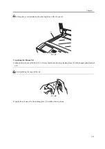
Page 29: ...ne oil F 1 27 3 Applying the Silicone Oil 1 Squeeze the silicone oil bottle 1 2 to 3 times thereby moistening cleaning tissue 2 with an appropriate amount of it Avoid inhaling the vapor of the oil F 1 28 2 Apply the silicone oil to the reading glass 1 with the cleaning tissue 1 ...

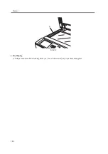
Page 30: ...Chapter 1 1 18 F 1 29 4 Dry Wiping 1 Using a fresh area of the cleaning tissue i e free of silicone oil dry wipe the reading glass 1 ...

Page 31: ...Chapter 2 Standards and Adjustments ...

Page 32: ......

Page 33: ...2 3 2 1 5 Eliminating the Tilt 2 3 2 1 6 Height 2 4 2 1 7 Right Angle 2 5 2 1 8 Angle Guide angle of opening of 70 deg 2 7 2 1 9 Magnification 2 8 2 1 10 Horizontal Registration 2 9 2 1 11 Leading Edge Registration 2 11 2 1 12 White Level 2 12 2 1 13 Adjusting the Hinge Pressure 2 13 2 2 Adjustment at Time of Parts Replacement 2 14 2 2 1 Overview 2 14 ...

Page 34: ......

Page 35: ...ning If it is 90 deg go to the next item of adjustment i e tray width 1 Bend over the edge of the rubber cover 1 and remove the 2 mounting screws 2 then detach the angle guide plate 3 F 2 1 2 1 3 Sensor Output 0004 9325 Make the following adjustments if you have replaced any of the following parts reader controller PCB post separation sensor PI7 read sensor PI8 delivery reversal sensor PI9 If you ...

Page 36: ...ntrol panel power switch and main power switch in sequence 11 Turn on the host machine s main power switch 2 Inch Configuration 1 Turn on the host machine and start its service mode Service Mode Press the User Mode key and press the 2 and 8 keys at the same time then press the User Mode key once again 2 Touch the following in sequence on the screen to bring up the Adjustment screen FEEDER FUNCTION...

Page 37: ...lls 1 at the left front and rear are not in contact with the reading glass 2 turn the fixing screw 3 found at the top of the left hinge F 2 4 2 1 7 Right Angle 0003 2252 The following steps adjust the relationship between the machine s original feed direction and the host machine s scanner system 1 Place the Test Chart in the machine and make a copy 2 Check the right angle of the image in relation...

Page 38: ... e if paper moves askew go to the next adjustment to remove the skew registration roller In principle the foregoing adjustment should correct the angle F 2 7 7 Remove the screw 1 and fit it and temporarily tighten it in the screw hole 2 F 2 8 if A B move up the plate 1 to make adjustments if A B move down the place 1 to make adjustments 8 When done move back the screw 1 to its initial hole and tig...

Page 39: ...e the length of the image in feed direction making sure that dimension a is as indicated If not go to step 5 standard a 1 mm F 2 11 5 Start service mode as follows press the User Mode key press the 2 and 8 keys at the same time and press the User Mode key once again 6 Make the following selections FEEDER ADJUST LA SPEED then change the setting to make adjustments To make the image on copy B longer...

Page 40: ... mm B 1 mm If not go to step 4 F 2 13 4 Start service mode as follows press the User Mode key press the 2 and 8 keys at the same time and press the User Mode key once again 5 Make the following selections COPIER ADJUST ADJ XY ADY Y DF Then change the setting to make adjustments A higher setting will increase the margin of A decreasing the margin of B in 0 1 m range 30 to 30 6 Make a copy of the Te...

Page 41: ...When done mount back the cover 7 Make a copy of the Test Chart once again and see that the image is as indicated 2 1 11 Leading Edge Registration 0003 2362 1 Obtain the Text Chart If the Text Chart is not available make one using A4 or LTR paper as follows F 2 16 2 Place the Text Chart in the original tray and make a copy of it at a 100 reproduction ratio 3 Check to see that dimension A of the Tes...

Page 42: ... DF WLVL1 to highlight 4 Press the OK key In response the machine runs an auto adjustment session and will indicate OK if it ends normally 5 Remove the paper from the copyboard glass and place it in the original pickup tray of the machine 6 Press DF WLVL2 on the touch panel to highlight 7 Press the OK key In response the machine will run an auto adjustment session duplexing stream reading 8 Press ...

Page 43: ...rizontal registration 5 leading edge registration 6 white level Post separation sensor 1 sensor output Read sensor 1 sensor output Post separation sensor 1 sensor output Original detecting volume 1 tray width Memo For details of these adjustments see the instructions given for basic adjustments If you have replaced the reader controller PCB or initialized EEPROM see the descriptions given under Af...

Page 44: ......

Page 45: ...Chapter 3 Error Code ...

Page 46: ......

Page 47: ...Contents Contents 3 1 User Error Code 3 1 3 1 1 Alarm Code 3 1 ...

Page 48: ......

Page 49: ...eparation sensor The 1st original does not reach the registration sensor xx11 The number of jam recovery sheets is greater than the number of originals In jam recovery mode the tray runs out of originals before as many as the number of recovery sheets 1 has been delivered xx13 An original has been pulled out The read sensor is off when the preceding original has been moved to a point of reading xx...

Page 50: ......

Page 51: ...Chapter 4 Outline of Components ...

Page 52: ......

Page 53: ...lectrical Components 4 1 4 1 1 Sensors 4 1 4 1 2 Motors Clutches Solenoids PCBs and Others 4 2 4 2 Variable Resistors VR Light Emitting Diodes LED and 4 4 4 2 1 Overview 4 4 4 2 2 ADF Driver PCB 4 4 4 2 3 Original Placement led PCB 4 4 ...

Page 54: ......

Page 55: ... J3 PI4 LGL sensor identficate LGL LTR size original WG8 5593 P005 4 1 paper present J3 PI5 Original placement sensor detects original on document tray WG8 5593 P005 7 0 paper present J2 0095 PI6 ADF cover open closed sensor detects cover open close WG8 5593 P004 0 0 open J2 0092 0093 0095 PI7 Separation rear sensor detects jam FM2 1022 P005 3 0 paper present J2 0001 0002 0042 0045 0046 0094 PI8 R...

Page 56: ...K E code Connector No M1 Pickup motor drives pickup system FK2 0204 P003 6 7 MTR CHK 0 J11 M2 Feed motor drives feed rollers FK2 0205 P003 4 5 MTR CHK 1 J8 M3 Delivery reversal motor drives delivery reverse roller reversal roller FK2 0217 P002 0 1 MTR CHK 2 J10 M4 Locking motor locks read roller 1 FK2 0207 P002 2 3 MTR CHK 3 E413 J9 Notation Name Description Part No I O FEEDER Conne ctor No JAM E ...

Page 57: ...ocking solenoid presses delivery reverse roller lower FK2 0210 SL CHK 0 J9 FM1 Cooling fan cools unit inside FK2 0208 P002 7 FAN CHK 0 J12 PCB1 ADF drive PCB controls ADF FM2 1021 VR1 Original width volume mesure original width FK2 1024 J3 Notificat ion Name Description Part No I O FEEDER PART CHK E code Connector No FM1 SL2 SL1 M4 M1 CL1 PCB1 M2 M3 VR1 ...

Page 58: ...not touch the check pins not indicated in the list They are intended for use at the factory and require special tools and high accuracy 4 2 2 ADF Driver PCB 0003 5539 Some LEDs emit dim light even when they area off The is a normal condition and must be kept in mind F 4 3 4 2 3 Original Placement led PCB 0003 5540 F 4 4 J4 J3 J2 J1 J5 J6 J14 J14 J12 J10 J9 J8 1 1 3 1 2 1 1 1 1 8 1 6 1 7 6 3 8 7 1 ...

Page 59: ...Chapter 5 System Construction ...

Page 60: ......

Page 61: ...ts 5 1 Basic Construction 5 1 5 1 1 Overview of the Electrical Circuitry 5 1 5 1 2 Inputs to the ADF Controller PCB 5 1 5 1 3 Outputs from the ADF Driver PCB 5 2 5 2 Product Specifications 5 4 5 2 1 Specifications 5 4 ...

Page 62: ......

Page 63: ... from sensors and the host machine to generate signals used to drive DC loads e g motor solenoid with the help of the CPU IC9 of the ADF driver PCB F 5 1 5 1 2 Inputs to the ADF Controller PCB 0002 7187 Inputs to the ADF Driver PCB 1 1 ADF driver PCB CPU IC9 5 VDC power supply IC10 CPU IC1 FLASH ROM IC3 EEP ROM IC4 IC5 IRC IC2 Reader controller PCB Power supply PCB Sensor Original indication LED P...

Page 64: ... present 0 reference light intensity adjustment signal J101 4 3 2 1 1 2 3 4 5V VR1 VR detects original paper width analog if paper is present 0 reference light intensity adjustment signal if paper is present 0 if paper is present 0 reference light intensity adjustment signal Original width volume 3 1 3 1 3 2 J1401 5V LGL sensor PI4 J3 7 9 8 J312 3 1 2 LG_S if paper is present 1 large size 3 1 2 4 ...

Page 65: ... M3 OUTA OUTA OUTB OUTB 24V J1002 6 5 2 1 3 4 1 2 5 6 4 3 Pickup motor J11 1 2 3 4 5 6 M1 OUTA OUTA OUTB OUTB 24V 1 2 FAN J12 Cooling fan FM1 Stamp solenoid SL1 24V J1B 2 1 STMP_SOL when 1 SL1 goes ON J111 1 2 2 1 Locking motor J9 3 4 5 6 M4 OUTA OUTA OUTB OUTB J902 4 3 2 1 1 2 3 4 ADF driver PCB Locking solenoid SL2 24V J9 1 2 R_SOL when 1 SL2 goes ON J901 2 1 1 2 ...

Page 66: ...2 mm must be fed individually 60 to 90 g m2 Color 64 to 128 g m2 Black and While w Color 50 to 128 g m2 Original size Size B6 A5 STMT to A3 11x17 Note If B6 cross feed direction only Feed Direction 128 0 to 432 0 mm extra length mode 630 mm Cross Feed Direction 139 7 to 297 0 mm 304 8 mm max Original placement Original Tray face up Original orientation Original Tray center reference Original readi...

Page 67: ...ns Combination of Configurations AB 13 B4 B4 A4R A4 B5 B5 A5 Original size identification width by pickup tray side guide platewidth by pickup tray side guide plate length by sensor and LGL sensor on tray Residual original detection yes in conjunction with host machine DONE stamp yes Note optionally set in service mode Original processing speed single sided 50 ipm double sided 25 ipm high speed do...

Page 68: ... To enable extra length mode use the following service mode item COPIER OPTION USER MF LG SET to enable select 1 to disable select 0 which is the default Operating environment same as host machine temperature humidity ...

Page 69: ...Feb 21 2005 ...

Page 70: ......

Reviews: