


CHAPTER 13 TROUBLESHOOTING
13-36
COPYRIGHT © 1999 CANON INC. CANON CLC1120/1130/1150 REV.0 MAR. 1999 PRINTED IN JAPAN (IMPRIME AU JAPON)
H. Electrical System
The copier's service mode is used to adjust its electrical mechanisms. Most of them are adjusted
at the factory, and require high precision. As a rule, do not make those adjustments that are not
discussed herein.
1
When Replacing the CPU PCB
1) Check the data of ADJUST and OPTION in service mode before replacement, and take notes.
Or, back up the data using the downloading tool.
2) Remove the CPU PCB.
3) Mount the new CPU PCB.
4) Remove the three flash memories and the memory PCB from the old CPU PCB, and mount
them to the new CPU PCB.
5) Turn on the power switch.
6) Select FUNCTION>CLEAR>DC-CON and R-CON in service mode, and set them to '1'.
7) Enter the data you took notes of in step 1).
8) Execute FUNCTION>CCD>CCD-ADJ in service mode.
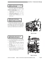
2
When Replacing the Flash Memory on the CPU PCB
1) Check the data of ADJUST and OPTION in service mode before replacement, and take notes.
Or, back up the data using the downloading tool.
2) Detach the old flash memory from the CPU PCB.
3) Mount the new flash memory to the CPU PCB.
4) Turn on the power switch.
5) Select FUNCTION>CLEAR>DC-CON and R-CON, and set them to '1'.
6) Enter the data you took notes of in step 1).
7) Execute FUNCTION>CCD>CCD-ADJ in service mode.
Summary of Contents for CLC 1120
Page 6: ......
Page 20: ......
Page 22: ......
Page 48: ......
Page 94: ......
Page 96: ......
Page 114: ......
Page 134: ......
Page 136: ......
Page 152: ......
Page 242: ......
Page 346: ......
Page 374: ......
Page 376: ......
Page 412: ......
Page 452: ......
Page 454: ......
Page 517: ......
Page 881: ......
Page 893: ......
Page 895: ......
Page 899: ......


