Canon BJC-6200 Service Manual Download Page 51

7.2 Service/Factory Test Printout

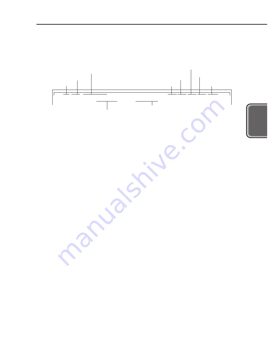
The header of the service/factory test printout shows the control ROM version, model setting, total printed
sheet count, total waste-ink absorption amount, and other information.

* USB serial No.
If multiple BJS-6200 printers are connected via USB, each printer will have a unique USB serial No. (in
accordance with USB standards) so that the computer can distinguish between them.

The unique USB serial No. is written in the EEPROM when the control board is manufactured. The USB
serial No. written in the EEPROM is not cleared even when the EEPROM is reset. Also, the USB serial

No. cannot be modified.

2-29

BJC-6200

Part 2: Troubleshooting

T

roub

leshooting

Installed cartridges

Model designation

Total printed sheet count with black/color

BJ cartridge

ROM version

Total printed sheet count with photo/color BJ cartridge

Total waste-ink amount (Waste-ink absorber's absorption capacity: %)

Serial No.* for USB

ROM Ver Vx.xx BJC-6200

Use Head <BC-30,BC-31> HeadTemp0=031.0 HeadTemp1=032.5 EnvironmentTemp=031.0 Bk=00000 C1=00257 Ph=00000 Sc=00000 ScC1=00000

Factory Area=01 00 00 00 00 01 1B 89 LostInkCount =03.9% Destination =01 USBSerialNo=(109BNF)

Total passed sheet count
with scanner cartridge

Unused

Unused

Figure 2-16 Service/Factory Test Printout (Sample)

Summary of Contents for BJC-6200

Page 1: ...QY8 1370 000 REVISION 0 COPYRIGHT 2000 CANON INC CANON BJC 6200 0400 AB 0 20 0 PRINTED IN JAPAN IMPRIME AU JAPON Apr 2000 ...

Page 2: ...042000 AB 0 20 0 ...

Page 3: ......

Page 4: ...duct names and company names described in this manual are the registered trademarks of the individual companies Copyright This manual is copyrighted with all rights reserved Under the copyright laws this manual may not be copied reproduced or translated into another language in whole or in part without the written consent of Canon Inc except in the case of internal business use Copyright 2000 by C...

Page 5: ...t and identifying the parts and units needing replacement Troubleshooting is described according to problem descriptions as well as error indications by the status indicator Part 3 Appendix Block diagrams information on the hardware technologies and pin configurations Disassembly and reassembly procedures are not fully covered in this manual Refer to the separate Parts Catalog instead Product Spec...

Page 6: ...ems 2 7 2 4 Troubleshooting With Error Indications 2 10 3 DISASSEMBLY AND REASSEMBLY 2 10 3 1 Cautions for Disassembly and Reassembly 2 10 3 1 1 Ink stains Ink path ink mist 2 10 3 1 2 Static electricity damage 2 10 3 1 3 Spur tips deformation 2 10 3 1 4 Feed gear damage 2 10 3 1 5 Tap screw removal and installation 2 11 3 2 Exploded View 2 13 3 3 Disassembly and Reassembly 2 13 3 3 1 Carriage loc...

Page 7: ...6 Ink Availability Check 2 31 7 7 Auto Print Head Position Adjustment 2 31 7 8 Power Off Carriage Lock Part 3 APPENDIX 3 1 1 TECHNICAL REFERENCE 3 1 1 1 Print Mode List 3 2 1 2 Purge Unit s Capping and Cleaning Functions 3 2 1 3 Cautions About the Inks 3 3 1 4 Operation with a Computer 3 3 1 4 1 Setting functions with the printer driver 3 4 1 5 Detection Functions by Sensors 3 5 1 6 Electronic Cir...

Page 8: ...Adjustment Pattern 2 20 Figure 2 12 Carriage Belt Tension Adjustment 2 21 Figure 2 13 Head Gap Adjustment 1 2 22 Figure 2 14 Head Gap Adjustment 2 2 27 Figure 2 15 Nozzle Check Pattern Printout Color Sample 2 29 Figure 2 16 Service Factory Test Printout Sample 2 30 Figure 2 17 EEPROM Information Printout Sample Part 3 APPENDIX 3 3 Figure 3 1 Printer Driver Utilities Sample 3 4 Figure 3 2 Sensor Lo...

Page 9: ...Part 1 PRODUCT SPECIFICATIONS 1 8 Table 1 1 PARTS CODE LIST Part 2 TROUBLESHOOTING 2 7 Table 2 1 ERROR INDICATIONS Part 3 APPENDIX 3 1 Table 3 1 PRINT MODE LIST 3 2 Table 3 2 INK CONSUMPTION DURING CLEANING GENERAL GUIDE V ...

Page 10: ......

Page 11: ...roduct Outline 1 2 2 SPECIFICATIONS 1 2 2 1 Printer Specifications 1 3 2 2 Paper Specifications 1 4 2 3 BJ Cartridge Specifications 1 5 2 4 Optional Scanner Cartridge Specifications 1 6 2 5 Printer and Scanner Drivers 1 7 3 PACKING CONFIGURATION 1 8 4 PARTS CODE LIST ...

Page 12: ......

Page 13: ...cartridge 6 Photo cartridge enables six color density matched photo quality printing 7 Black cartridge contains pigment colored ink for truer black text printing 8 Highly precision ink low detection with an optical system and dot count 9 Stabilized image printing with the easy to use automatic print position adjustment 1 1 BJC 6200 Part 1 Product Specifications Product Specifications Operation Pan...

Page 14: ...aper Max 10 mm Approx 80 sheets of high quality paper Front cover open sensor Printing position sensor BJ cartridge sensor Paper sensor BJ cartridge ID sensor Waste ink capacity sensor No ink sensor Paper width sensor None Internal temperature sensor Approx 45 dB A Sound pressure level conforms to ISO 9296 During operation Temperature 5 C 35 C 41 F 95 F Humidity 10 90 RH No condensation During non...

Page 15: ...er Glossy film Transparency film Back print film Banner T shirt transfer Photo glossy card Postcard Envelope Size A4 B5 LTR LGL A5 Portrait Landscape A4 LTR A4 LTR A4 LTR A4 LTR A4 LTR A4 LTR A4 LTR A4 LTR 120 mm 216 mm 100 mm 148 mm 241 mm 105 mm 220 mm 110 mm LC 301 HR 101 GP 301 HG 201 CF 102 BF 102 BP 101 TR 201 FM 101 COM 10 DL size ASF Capacity Approx 10 mm or less Approx 100 sheets of 64 g ...

Page 16: ...ure 1 2 Printable Area Construction Head Ink colors Tank Weight Service Life Printable Sheets Black BJ Cartridge BC 30 Detachable ink tank 160 nozzles Vertical array Bk 160 nozzles 1 Pigment black BCI 3BK 60 g w o ink tank Approx 5000 sheets Approx 500 sheets tank 1 500 black characters page Color BJ Cartridge BC 31 Detachable ink tank 144 nozzles Vertical array C M Y 48 nozzles 3 Dye C M Y BCI 3C...

Page 17: ...Specifications Designation Type Resolution dpi Imaging Sensor Light Source Scanning System Direction Document Feeding Interface External Dimensions Weight Other Specifications Scanning Time reference IS 32 Cartridge replacement type color scanner 90 90 180 180 200 180 300 360 360 360 720 720 256 pixel linear single line CCD RGB Red Green Blue RGB switching progressive scanning Document inserted in...

Page 18: ...c updater 1 0 Common driver for Windows 95 98 NT 4 0 2000 Operates in Nibble or ECP mode 1 Window Drivers Win 95 98 BJ raster printer driver IEEE 1284 8 bit parallel and USB supported Win NT 4 0 BJ raster printer driver Win 2000 BJ raster printer driver Windows 95 98 NT 4 0 2000 scanner driver IS Scan 2 Macintosh Drivers Mac BJ printer driver USB Mac scanner driver IS Scan USB Part 1 Product Speci...

Page 19: ...n included 1 7 BJC 6200 Part 1 Product Specifications Product Specifications Quick Start Guide Ink Tanks User Manuals Cartridge Container BJ Cartridges Printer Power Cord Output Tray Packing Materials Tape Packing Materials Packing Materials Tape Tape Tape Figure 1 4 Packing Configuration ...

Page 20: ...rtridge Cartridge storage box Scanner cartridge A4 LTR scanning holder Black Color Photo Black Cyan Magenta Yellow Photo black Photo cyan Photo magenta Scanning holder Standard white sheet Designation BJC 6200 BC 30 BC 31 BC 32 Photo BCI 1BK BCI 3C BCI 3M BCI 3Y BCI 3PBK Photo BCI 3PC Photo BCI 3PM Photo SB 30 IS 32 SH 101 Product Code Q30 3310 Q30 3312 F45 1471 F45 1481 F45 1501 F47 2171 F47 2181...

Page 21: ...embly 2 23 4 OPERATION CHECK AFTER DISASSEMBLY AND REASSEMBLY 2 23 4 1 Check Procedure 2 24 5 TRANSPORTING THE PRINTER 2 24 5 1 Preparation for Transport 2 25 6 PARTS REPLACEMENT PERIODIC INSPECTIONS TOOLS 2 25 6 1 Parts Replacement 2 25 6 2 Periodic Inspections 2 25 6 3 Tool List 2 26 6 4 Operation with the Printer s Operation Panel 2 28 7 SERVICE RELATED FEATURES 2 28 7 1 Service Mode Operations...

Page 22: ......

Page 23: ...umber of times the indicator blinks in orange and or green 1 1 1 Status display via the indicator The operation status indicated by the indicator is as follows 2 1 BJC 6200 Part 2 Troubleshooting Troubleshooting POWER button Indicator RESUME button Figure 2 1 Operation Panel Indicator Green light Green blinking OFF Operation Status Power ON Power ON operation in progress power OFF operation in pro...

Page 24: ...lever is not set properly The print head needs cleaning The ink cartridge is empty The BJ cartridge has not been used for a prolonged period The recommended paper is not being used The print head is installed in the wrong position The orange tape is still affixed to the print head The print head position adjustment has not been done Solution Connect the AC cord to a power outlet that supplies the ...

Page 25: ...ng No error indication see page 2 9 AC power connection AC power supplied With the POWER button To next page MPU printer controller initialization ROM check DRAM check Ink sensor check waste ink full check internal temperature sensor TH501 check Ink sensor error EEPROM read Power ON Indicator blinks ...

Page 26: ...ong blink in green repeatedly See page 2 8 Indicator repeats Blinks 2 times in orange repeatedly See page 2 8 Indicator repeats Blinks 8 times in orange green followed by a long blink in green repeatedly See page 2 9 Indicator repeats Blinks 4 times in orange green followed by a long blink in green repeatedly See page 2 8 Is there paper inside the printer Any ROM RAM errors are indicated as descri...

Page 27: ...lation Cartridge not recognized Not installed properly The sensor will determine if the front cover is open or closed Indicator repeats Blinks 10 times in orange green followed by a long blink in green repeatedly See page 2 9 From preceding page ASF sensor check No BJ cartridge check ASF sensor error Cleaning Cover open check Carriage moves to cartridge replacement position Open Open Closed I F bu...

Page 28: ...per transport parts The paper is already soiled when it reaches the platen Deformed spur tips Paper thickness lever not properly set The nozzle check pattern s printout is misaligned Guide shaft not greased properly Faulty carriage motor Ink sensor control board LF motor 2 step gear purge unit sheet feeder unit orange cap still attached to the print head Solution Replace faulty part Replace faulty...

Page 29: ... not be correct Table 2 1 ERROR INDICATIONS Indicator Error Description Probable Cause and Suspected Parts Blinking Code User Recoverable Errors Paper feed error Cause Paper feed does not work even when the paper feed operation is attempted Suspect Paper feed section sheet feeder unit paper end sensor control board Paper jam error Cause The paper is not ejected even when the paper ejection operati...

Page 30: ...ecause the home position sensor is faulty disconnected etc Suspect Home position sensor purge unit carriage motor paper feed motor control board carriage ribbon cable carriage board DC cable 5400 Internal temperature sensor error Cause The temperature sensor TH501 on the control board is faulty disconnected etc Suspect Thermistor control board 5B00 Waste ink full error Cause The waste ink absorber...

Page 31: ...he scanner cartridge Suspect Scanner cartridge control board 5000 Recovery system error Cause While AP motor or LF motor runs the PG sensor does not turn ON or OFF Suspect Purge unit AP motor LF motor control board Internal Error Ink sensor Cause The check by the ink sensor during initialization indicates that ink is available when there is none The ink sensor does not check the ink until the AC p...

Page 32: ...cartridge on the carriage 3 1 3 Spur tips deformation Be careful not to deform the spur tips The spur tips contact the paper after the printing Since the spur tips contact area is small any ink adhering to the spur will be a minuscule amount that can be wiped off by the spur cleaner It therefore will not soil the paper However if the spur s tips are bent of out of shape the contact area with the p...

Page 33: ...3 2 Exploded View Figure 2 2 Exploded View BJC 6200 Part 2 Troubleshooting 2 11 Troubleshooting ...

Page 34: ......

Page 35: ...ormally released However if the printer does not operate properly you can release the carriage lock manually as shown in the illustration below Remove the cartridge and while holding down the purge unit s lever move the carriage to the left This releases the carriage lock 3 3 2 Removing and installing tap screws The printer uses tap screws to fasten the printer unit and base The removed tap screws...

Page 36: ...ter unit Remove the printer unit as shown in the figure below 1 First remove the two screws securing the printer unit and bottom case 2 Release the bottom case s two hooks at the back of the printer unit Arrows 1 and 2 3 Hold the two handles on the sides of the printer unit and lift up at an angle as shown by arrow 3 Part 2 Troubleshooting BJC 6200 2 14 Figure 2 4 Upper Cover Unit Removal and Inst...

Page 37: ...ler unit This will make removal easier 3 3 6 Spur positions on the spur base unit The figure below shows the position of the spurs on the spur base The side bottom where the spurs are installed is shown If you removed any of the spurs by mistake use this diagram to install then at the correct position 2 15 BJC 6200 Part 2 Troubleshooting Troubleshooting Figure 2 6 Removing the Pressure Roller Unit...

Page 38: ...ter frame is loosened the head gap will change and head gap adjustment will be necessary The set screw is painted in red to distinguish it from the other screws and to prevent accidental loosening If you have loosened it by mistake do the head gap adjustment as described in 3 4 6 Adjusting the head gap on page 2 21 Part 2 Troubleshooting BJC 6200 2 16 Set screw Set screw ASF unit Figure 2 8 Removi...

Page 39: ...d 2 min Tools Required 2 sheets of B5 or larger paper Timing After idler pulley installation removal After control board replacement or waste ink absorber replacement After replacement disassembly of carriage unit parts After loosening the head gap set screws Parts to be greased Adjustment Belt tension EEPROM setting BJ cartridge printing position adjustment Head gap See page 2 18 Time Required 1 ...

Page 40: ...ny grease on the wiper and cap Part 2 Troubleshooting BJC 6200 2 18 Carriage shaft friction surface No dripping Floil 946P Rear of carriage rail Apply on entire surface Approx 48 mg Molykote PG 641 Feed roller friction surfaces Three places on back of platen Approx 14 mg x 3 places Molykote PG 641 Cam friction surface Approx 27 mg Molykote PG 641 Pick up roller friction surface Approx 7 mg Molykot...

Page 41: ... and the ink will soil the platen 2 19 BJC 6200 Part 2 Troubleshooting Troubleshooting LED Calibration 360 dpi vertical position adjustment 360 dpi bi directional rough adjustment 360 dpi bi directional fine adjustment 180 dpi bi directional rough adjustment 180 dpi bi directional fine adjustment 360 dpi horizontal position forward direction rough adjustment 360 dpi horizontal position forward dir...

Page 42: ...k 2 After waste ink absorber replacement Clear the EEPROM s waste ink counter Once the data in the EEPROM is reset a test printout cannot be used to confirm the old data Be sure to print the data before resetting the EEPROM The various settings except the model setting sheet count and waste ink amount will be reset The various settings and waste ink amount stored in the old EEPROM cannot be writte...

Page 43: ...sen the red set screws on both sides of the printer chassis by a half rotation from the fully tightened position 4 Set the paper thickness lever to the down position for thick paper Before doing the adjustment make sure the gap gauge is not deformed and that no foreign matter is adhering to it or to the platen 2 21 BJC 6200 Part 2 Troubleshooting Troubleshooting Red set screw Red set screw Head ga...

Page 44: ...o position B2 Align the ink sensor s edge with the carriage s left end 9 Install a black BJ cartridge without ink tank in the carriage 10 Move the paper thickness lever up and down two or three times then while holding the lever in the normal paper up position tighten the red set screw on the left end 11 Remove the black BJ cartridge 12 Loosen the red set screw on the right end by a half turn Then...

Page 45: ...ol board or the ink absorber the following check procedure is also necessary in addition to 1 above 2 23 BJC 6200 Part 2 Troubleshooting Troubleshooting After control board replacement After waste ink absorber replacement The service factory test printout must show the correct ROM version and model designation It must also show the printed sheet count and that the total waste ink amount has been c...

Page 46: ...w 1 With the printer turned on open the front cover and move the carriage to the cartridge replacement position 2 Remove one cartridge from the carriage and put it in the cartridge container 3 Turn off the printer by pressing the POWER button 4 Then from Service Mode conduct the power off carriage lock procedure For details refer to 7 1 Service Mode Operations on page 2 28 5 Disconnect the interfa...

Page 47: ...to Magenta BCI 3M Photo None Ordinary Tools Phillips screwdriver Blade screwdriver Needle nosed pliers Tweezers Flat brush Multi meter Remarks For the removal and installation of screws For the removal of plastic parts For the removal and installation of springs For the disconnection and connection of flexible cables etc For applying grease For troubleshooting Special Tools Part No Gap gauge 2 3 m...

Page 48: ...nd release after the green indicator blinks twice The printer will then start printing the nozzle check pattern If any printing defects appear in the test printout clean the BJ cartridges If printing defects persist even after cleaning the BJ cartridges five times or more replace the BJ cartridges Printing the nozzle check pattern requires B5 or larger paper If the paper s width is narrower than t...

Page 49: ...inting by the 48th nozzle Black 48 nozzles 48 nozzles 48 nozzles Yellow Cyan Magenta 160 nozzles Large dot printing Small dot printing Color BJ cartridge Small dot printing by the 1st nozzle Small dot printing by the 48th nozzle X1 X2 X3 X4 X5 X6 B1 B2 360 dpi vertical position 360 dpi bi directional 180 dpi bi directional 360 dpi horizontal position forward direction 360 dpi horizontal position r...

Page 50: ...er of times indicated below to set the product type During the initialization the green indicator blinks Each time the RESUME button is pressed the indicator s color toggles between orange and green After selecting the model press the POWER button to finalize the setting After the printer executes the function it will turn off Before entering the service mode install the BJ cartridges The service ...

Page 51: ...M is not cleared even when the EEPROM is reset Also the USB serial No cannot be modified 2 29 BJC 6200 Part 2 Troubleshooting Troubleshooting Installed cartridges Model designation Total printed sheet count with black color BJ cartridge ROM version Total printed sheet count with photo color BJ cartridge Total waste ink amount Waste ink absorber s absorption capacity Serial No for USB ROM Ver Vx xx...

Page 52: ...sensor error 5910 35 39 31 30 Waste ink full error 5B00 35 42 30 30 Pump sensor error 5C00 35 43 30 30 EEPROM Read Write error 6800 36 38 30 30 EEPROM Information Hex Address 0 1 2 3 4 5 6 7 8 9 A B C D E F 00000000 05 20 00 0A 00 00 B8 83 00 0C 9F 40 09 35 1C 28 00000010 00 00 00 00 2A 6A 51 A1 38 54 AA A0 1E 16 DA 3C 00000020 35 6C B7 AB 33 BC E9 71 32 DD 02 0C 00 00 00 00 00000030 14 00 0A 07 0...

Page 53: ...ting the model confirm it with the service factory test printout 7 6 Ink Availability Check When this function is selected the printer scans the carriage to check for ink in the ink tank s ink compartments The result is printed out Whether the ink sensor is working properly can be confirmed by 1 Installing an empty ink tank in the BJ cartridge 2 Using this Service Mode function and print out the r...

Page 54: ...Part 2 Troubleshooting BJC 6200 2 32 This page intentionally left blank ...

Page 55: ...ions by Sensors 3 5 1 6 Electronic Circuit Description 3 6 2 CONNECTOR LOCATIONS AND PIN CONFIGURATIONS 3 10 2 1 Carriage Board 3 11 2 2 BJ Cartridge 3 12 2 3 Scanner Cartridge Optional 3 13 2 4 AC Adapter 3 13 2 5 DC Power Cable 3 14 2 6 Carriage Motor 3 14 2 7 Paper Feed Motor 3 14 2 8 ASF Motor 3 15 2 9 Ink Sensor 3 15 2 10 Printing Position Sensor 3 15 2 11 Purge Sensor Connector 3 17 2 12 Cir...

Page 56: ......

Page 57: ... 1 pass uni directional Pattern High speed Plain paper 1 pass bi directional 1 pass bi directional High quality 2 passes bi directional Auto Plain paper 1 pass bi directional 1 pass bi directional High quality 2 passes bi directional Photo Color Cartridge Printing Quality Dithering Paper Type High speed Standard Faster Speed Standard Higher Quality High Quality Highest Quality 180 180 L R 360 360 ...

Page 58: ...n 56 81 5 and isopropyl alcohol 67 63 0 3 Cyan magenta photo cyan photo magenta photo black inks Contain glycerin 56 81 5 isopropyl alcohol 67 63 0 ethylene glycol 107 21 1 and diethylene glycol 111 46 6 Do not consume the inks or get it into your eyes Should ink get into your eyes rinse with lots of water and consult a doctor Should a large amount of ink be consumed by mistake promptly see a doct...

Page 59: ...t Disabled Special Menu for Users User or Service Mode The Special Menu for users can be accessed by holding down the Shift key and clicking the Custom Settings button Economy Cleaning Factory default Disabled The cleaning operations after the AC power is connected and the power turned on for the first time is disabled When the printer is being repaired or when it turns on in tandem with the compu...

Page 60: ... to detect the printer s operating status Part 3 Appendix BJC 6200 3 4 Purge sensor Purge unit Printing position sensor Carriage unit Paper end sensor Home position sensor Carriage unit Ink sensor Pick up roller sensor Internal temperature sensor Figure 3 2 Sensor Locations ...

Page 61: ...r Paper end sensor PS401 Pick up roller sensor PS402 HVH HVDD VHLED VDD DTCK ST0 LNST RST SCHKR PO0 INTP100 PO1 INTP101 CR_CLK CR_STB CR_DATA LF_CLK LF_STB LF_DATA PD2 ANI1 POWER switch SW401 RESUME switch SW402 USB interface CN305 Ink sensor CN401 Ink sensor ST1 TST2 ST2 SOT ST3 ST4 TST3 ST5 TST4 ST6 TST5 PC0 PO2 INTP102 Front cover switch SW403 PA0 PA1 Power indicator Error indicator LED401 Home...

Page 62: ...or scanner cartridge optional Print position sensor CN401 CN4 BJ cartridge CN6 Paper feed motor ASF unit Paper end sensor CN504 CN402 AC adapter Ink sensor Home position sensor Pick up roller sensor Motor control Mechanical control Internal temperature sensor 24V DC Interface control AC 5V DC Control Section Indicator Control button Front cover switch Indicator control Carriage unit Parallel USB 3...

Page 63: ...Nibble Mode HostClk Data1 Data2 Data3 Data4 Data5 Data6 Data7 Data8 PrtClk PrtBusy AckDataReq Xflag HostBusy Undefined Gnd Gnd Vcc Signal Gnd Signal Gnd Signal Gnd Signal Gnd Signal Gnd Signal Gnd Signal Gnd Signal Gnd Signal Gnd Signal Gnd Signal Gnd Signal Gnd INIT DataAvail Undefined Undefined Undefined 1284Active ECP Mode HostClk Data1 Data2 Data3 Data4 Data5 Data6 Data7 Data8 PeriphClk Periph...

Page 64: ...5VDC Pin No 1 2 3 4 Signal CRA CRB CRA CRB IN OUT OUT OUT OUT OUT Function Carriage motor phase A Carriage motor phase B Carriage motor phase A Carriage motor phase B Pin No 1 2 3 4 Signal LFA LFB LFA LFB IN OUT OUT OUT OUT OUT Function Paper feed motor phase A Paper feed motor phase B Paper feed motor phase A Paper feed motor phase B Pin No 1 2 3 4 Signal ASFA ASFB ASFA ASFB IN OUT OUT OUT OUT OU...

Page 65: ...Clock signal for transferring the serial data GND Serial data left carriage transferred according to the clock signal GND Head temperature sensor s diode anode in the head Head temperature sensor s diode cathode Home position sensor signal pull up voltage Home position sense signal Drive voltage to the print position sensor s LED Voltage varying according to the reflected light amount CN2 Pin No 2...

Page 66: ...ble Connector CN4 CN5 Left Right Cartridge CN6 Print Position Sensor Connector Part 3 Appendix BJC 6200 3 10 1 18 CN3 1 27 1 27 CN1 CN2 1 4 CN6 1 3 2 4 31 33 34 32 1 3 2 4 31 33 34 32 CN4 CN5 Figure 3 7 Carriage Board Pin No 1 2 3 4 Signal REGA SNSG REGC LGND IN OUT OUT OUT Function Drive voltage to the print position sensor s LED GND Voltage varying according to the reflected light amount GND Pin...

Page 67: ...ntification information and rank resistance Rear heater selection signal for the head block s upper nozzles 1 8 17 24 145 152 Head s logic driving voltage 5 V Clock signal for transferring the serial data Head s logic driving voltage HVDD s GND Front heater selection signal for the head block s upper nozzles 1 8 17 24 145 152 Front heater selection signal for the head block s lower nozzles 9 16 25...

Page 68: ...3 N C RST DIA DIK IN OUT IN IN OUT IN IN IN OUT IN IN IN IN IN IN IN IN IN IN OUT OUT Function 24 V for LED Unused GND Unused GND Scanned image s serial data GND Write clock for setting the internal resistor 5 V Scanned image s serial data clock GND Enable signal for setting the internal resistor GND Internal resistor setting data Scanner cartridge detection and recognition Scan start signal 1 lin...

Page 69: ...1 7 2 8 3 5 6 Figure 3 10 AC Adapter Pin No 1 2 3 4 5 6 7 8 Signal 24V 5V 5 GND HGND IN OUT OUT Function N C N C 24V DC N C 5V DC GND N C GND 3 4 1 5 5 1 Figure 3 11 DC Power Cable Pin No 1 2 3 4 5 Signal 24V HGND 5V GND 5V IN OUT OUT OUT Function 24V DC GND GND 5V DC ...

Page 70: ...T IN IN IN IN Function Carriage motor phase A Carriage motor phase B Carriage motor phase A Carriage motor phase B Pin No 1 2 3 4 Signal LFA LFB LFA LFB IN OUT IN IN IN IN Function Paper feed motor phase A Paper feed motor phase B Paper feed motor phase A Paper feed motor phase B Pin No 1 2 3 4 Signal ASFA ASFB ASFA ASFB IN OUT IN IN IN IN Function ASF motor phase A ASF motor phase B ASF motor pha...

Page 71: ...ltage varying according to the reflected light amount 1 4 Figure 3 16 Print Position Sensor Pin No 1 2 3 4 Signal REGA SNSG REGC LGND IN OUT OUT OUT Function Drive voltage to the print position sensor s LED GND Voltage varying according to the reflected light amount GND 1 3 1 3 1 3 Figure 3 17 Purge Sensor Pin No 1 2 3 Signal VSEN SNS_DO_RUCK IN OUT IN OUT Function Photo LED drive voltage in the i...

Page 72: ...Part 3 Appendix BJC 6200 3 16 This page intentionally left blank ...

Page 73: ...B3 HDATA0 DIK1 DIA1 SNSG HENB4 HENB5 LGND HSEL2A1 HSEL1A1 HSEL2B1 1 2 3 4 5 6 7 8 9 10 11 12 13 14 15 16 17 18 19 20 21 22 23 24 25 26 27 28 29 30 31 32 33 34 CN5 C5 1µF 50V HSEL1B1 DIR HSEL1A1 HSEL2B1 HVH SUBH1 LGND HLAT HCLOCK1 HSEL2A1 ODD EVEN BENB0 BENB1 HENB4 HENB5 HENB4 HENB5 HDATA1 HRSTX DIA1 DIK1 HGND HVDD 1 2 3 4 5 6 7 8 9 10 11 12 13 14 15 16 17 18 19 20 21 22 23 24 25 26 27 28 29 30 31 ...

Page 74: ...D15 97 ROM_D7 96 ROM_D0 95 ROM_D14 94 ROM_D8 93 ROM_D6 92 ROM_D1 91 ROM_D13 90 ROM_D9 89 ROM_D5 88 ROM_D2 87 ROM_D12 86 ROM_D10 85 ROM_D4 84 ROM_D3 83 ROM_D11 82 PD0 81 NTEST2 80 NTEST1 TST7 79 GND_INT2 78 3 3VDD_INT2 77 GND5 76 USB_DX 75 USB_D 74 STB 73 IF_D0 72 IF_D1 71 IF_D2 70 IF_D3 69 IF_D4 68 IF_D5 67 IF_D6 66 IF_D7 65 ACK 64 BUSY 63 PE 62 SLCT 61 FAULT 60 AFXT SCK 59 INIT 58 5VDD2 57 SELIN ...

Page 75: ...5 4 NNCD6 8G ZD206 4 5 2 3 1 ZD207 NNCD6 8G HSEL2A0 4 5 2 3 1 ZD201 NNCD27G SUBH1 HVH HENB2 HENB3 BENB0 HRSTX ODD HSEL1A0 HCLOCK0 HPA HSEL2A1 HSEL2B1 HSEL1A1 HDATA1 HDATA0 REGC SNS_HP HSEL1B1 REGA HSEL2B0 HCLOCK1 HSEL1B0 HLAT HENB1 DIR BENB1 EVEN HENB5 HENB4 DIK0 1 2 3 RN2415 Q203 24V 2 1 C202 1000P 50V 1 2 220 1 8W R262 2 1 R260 1K 1 16W REGI REGC 5V 3 3V 4 5 2 3 1 NNCD6 8G ZD209 DIK1 4 2 1 3 6 8...

Page 76: ...19 1 2 100 1 16W R317 IFCONT 8 0 IFCONT8 IFCONT7 IFCONT6 IFCONT5 IFCONT4 IFCONT3 IFCONT2 IFCONT1 IFCONT0 D2 D3 D4 D5 D6 D7 D8 STB J36P 1 CN304 J36P 14 CN304 J36P 31 CN304 J36P 10 CN304 J36P 11 CN304 J36P 12 CN304 J36P 13 CN304 J36P 32 CN304 J36P 15 CN304 J36P 16 CN304 J36P 17 CN304 J36P 18 CN304 J36P 19 CN304 J36P 20 CN304 J36P 21 CN304 J36P 22 CN304 J36P 23 CN304 J36P 24 CN304 J36P 25 CN304 J36P ...

Page 77: ...9K 1 16W R404 2 1 TBPS1473J475H5Q TH401 2 1 0 01U 50V C408 1 2 3 Q401 RN2415 2 1 R408 47K 1 16W FB 2 1 FB403 BK1608HS601 3 2 1 RN2415 Q402 5V 1 2 47K 1 16W R409 1 2 3 FP1L3N Q403 2 1 R410 47K 1 16W J3P 1 CN401 J3P 3 CN401 INKS 2 1 150 1 4W R413 1 2 68K 1 16W R412 5V NC TEST VCC GND CS DO SK DI 5 4 6 3 7 2 8 1 S 93C56AFJ TF IC402 2 1 0 1U 25V C411 5V 2 1 SEC2494C LED401 3 4 SEC2494C LED401 SKQNLA F...

Page 78: ...PGND3 RS_C OUT_C RS_B VMC VMD OUT_D RS_D PGND2 OUT_D CCP_C CCP_B CR_CD VREF_CD OUT_B VMB 1 2 10 11 12 13 14 15 16 17 18 19 3 20 21 22 23 24 25 26 27 38 28 29 30 31 32 33 34 35 36 4 5 6 7 8 9 37 TB62201AF IC401 24U 1 2 R509 0 75 1 4W 24U 1 2 R508 390 1 16W 1 2 680P 50V NOTMNT C517 2 1 1000P 50V C516 1 2 2K 1 16W R506 2 1 C508 0 22U 50V 1 2 C509 0 015U 50V 2 1 0 75 1 4W R511 1 2 R515 0 75 1 4W J4P 1...

Page 79: ......

Page 80: ...PRINTED IN JAPAN IMPRIME AU JAPON CANON INC The printing paper contains 100 waste paper ...

Reviews: