3
Parts names and functions
24
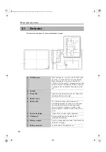
The detector is designed to capture radiographic images.
3.1
Detector
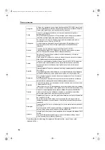
A
POWER switch
When the detector is off, press the POWER switch
(for at least 0.5 seconds) to turn on the detector.
When the detector is on, press and hold the
POWER switch (for at least 3 seconds) to turn off the
detector, or press and hold the POWER switch (for
1 second or less) to establish the communication
link.
B
Speaker
C
Power LED
Lights up when the detector turns on. Shows the
remaining battery pack charge.
D
READY switch
E
READY LED
This LED lamp flashes while the detector is
transitioning to exposure ready status, and lights
up when the detector enters exposure ready
status. Also flashes (approx. 3 seconds) when
detector linkage is initiated. Flashes in the case of
errors.
F
Error code display
If errors occur, an error code is displayed.
G
IR data port
Communication port for the detector link
(registration/connection)
H
Wireless module
Transmits image data with wireless communication
(IEEE 802.11a/b/g/n).
I
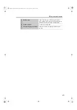
Battery cover lock
Locks or unlocks the battery cover.
A
L
B
C
D
E
G
K
I
J
F
H
000_DIA-2019-002-E04_AX-B2735W.book Page 24 Friday, November 27, 2020 12:22 PM
Summary of Contents for AX-B2735W
Page 6: ...Conventions 6 000_DIA 2019 002 E04_AX B2735W book Page 6 Friday November 27 2020 12 22 PM ...
Page 21: ...2 Introduction 000_DIA 2019 002 E04_AX B2735W book Page 21 Friday November 27 2020 12 22 PM ...
Page 41: ...6 Maintenance 000_DIA 2019 002 E04_AX B2735W book Page 41 Friday November 27 2020 12 22 PM ...
Page 43: ...7 Specifications 000_DIA 2019 002 E04_AX B2735W book Page 43 Friday November 27 2020 12 22 PM ...
Page 59: ...000_DIA 2019 002 E04_AX B2735W book Page 59 Friday November 27 2020 12 22 PM ...

