background image

E5

1


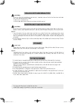
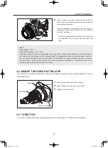
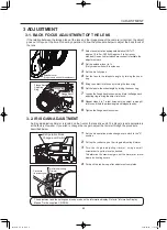
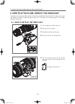
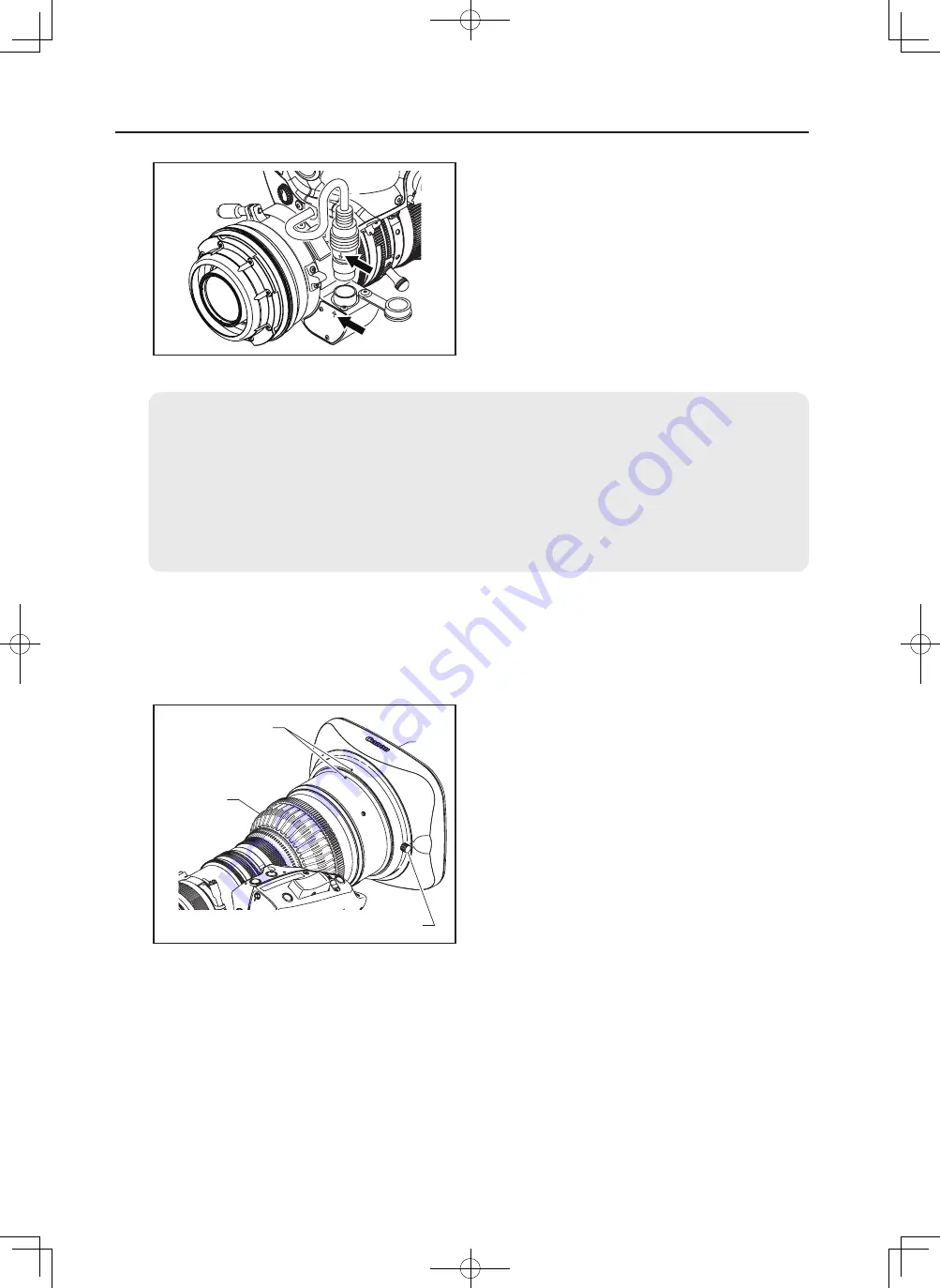
Fit the hood on the front of the lens barrel.

2


Align the index on the hood and lens barrel.

3


Tighten the hood lock knob.

2-3. TURN IT ON

Turn on the camera and power supply equipment on, and the power of the lens will be supplied.

2-2. MOUNT THE HOOD ON THE LENS

The lens cap is attached to the lens at the factory. Please remove the lens cap and attach the hood as 
instructed below.

2 HOW TO MOUNT

4


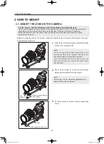
When the lens is mounted, connect the cable from the 
drive unit to a power supply equipment such as camera 
or external power supply.

Or if the camera can be powered from the PL mount, 

connect the cable from the drive unit to the connector 

below the lens mount

* Connect the cable so that the arrow on the connector of 

the cable aligns with the arrow of the connector of the 
lens.

NOTE
Rated voltage: 12 VDC
Normal operation range: 10 to 17 VDC
If a battery or adapter is used, the output voltage may be higher than the rated voltage depending on the manufacturers 
and therefore the above voltages must be observed strictly. If a voltage outside the normal operation range is used, the 
drive unit may be damaged. And the lens power input has the positive and negative polarities. Make sure to connect 
the power cable to the correct polarity when connecting the batteries or the adaptors. Connecting the cable to the 
incorrect polarity may cause the damage to the product.

Index

Hood

Lens Barrel

Hood Lock Knob

BT1-B051-E_E_CC.indd   5

2020/02/04   11:02:21

Summary of Contents for 4573C002

Page 1: ...s operation manual before using the product Keep the manual in place for future reference 在使用本产品之前 请务必先仔细阅读本使用说明书 请务必妥善保管好本书 以便日后能随时查阅 保留备用 请在充分理解内容的基础上 正确使用 CN7x17 CN10x25 变焦镜头 取扱説明書 レンズ編 OPERATION MANUAL LENS 使用说明书 镜头汇编 JP EN CN RU KZ BT1 B051 E_J_CC indd 1 2020 02 04 9 05 25 ...

Page 2: ...ENGLISH VERSION BT1 B051 E_E_CC indd 1 2020 02 04 11 02 01 ...

Page 3: ... Radio Interference Regulations CAN ICES 3 B NMB 3 B Only for European Union and EEA Norway Iceland and Liechtenstein This symbol indicates that this product is not to be disposed of with your household waste according to the WEEE Directive 2012 19 EU and national legislation This product should be handed over to a designated collection point e g on an authorized one for one basis when you buy a n...

Page 4: ...e mentioned above may be required depending on the specifications of your unit For details contact your dealer or Canon Inc The illustrations in this book show CN7x17 KAS unless otherwise specified Actual forms may vary depending on models and specifications Two types such as the EF mount and the PL mount are available for this product Illustrations in this manual are for the EF mount lens unless ...

Page 5: ...ns It may injure your eyes 3 Be sure to hold the connector when disconnecting the cable Pulling on the cable may sever or damage it and pose a risk of a fire or electric shocks from a short circuit CAUTION 1 Be careful not to drop the product when carrying it Dropping the product may cause injury 2 Ensure that all mountings are securely tightened If a mounting becomes loose parts may fall off and ...

Page 6: ...tached poses a risk of fire if the lens concentrate light in direct sunlight NOTE Immediately wipe off any moisture on the lens from misty or foggy environments using a dry cloth Seal the lens in a plastic bag with a desiccant preferably new to prevent moisture inside Otherwise it may cause the mold or the malfunction of the product TO THE CUSTOMER 1 Canon shall bear no responsibility for damage r...

Page 7: ...BT1 B051 E_E_CC indd 6 2020 02 04 11 02 05 ...

Page 8: ...STMENT 5 1 ZOOM OPERATION 5 2 FOCUS OPERATION 5 3 IRIS OPERATION 5 4 EXTENDER OPERATION Only models with built in extender 5 5 MACRO OPERATION 5 6 SWITCH OPERATIONS 6 1 HOW TO DETACH THE DRIVE UNIT 6 2 HOW TO ATTACH THE DRIVE UNIT 6 3 AUTOMATIC ADJUSTMENT OF THE MECHANICAL END 4 MODE SETTING 4 1 OPERATION MODES 4 2 SETTINGS IN BASIC MODE 4 3 SETTINGS IN FULL MODE 4 4 SETTINGS IN ANALOG MODE 7 PROD...

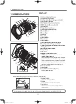
Page 9: ...r focusing Connector has also a function to operate the iris through a focus control accessory and a dedicated cable and a function to interface with various virtual systems It can output each positioning signal of zoom focus and iris Hood Lock Knob Lens Holder Lens Cable Connector 12 pins NOTE PL mount lens only Display Switch Used to turn the display ON OFF Display It turns off if left for 2 min...

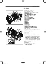
Page 10: ...the Drive Unit Fixing Screws Max Zoom Speed Volume 12 pin Cable VTR Switch Remote Connectors 20 pin NOTE Only Connector can be used as the iris remote or virtual output port Use these connectors to connect the control accessory equipped with a 20 pin connector for zooming or focusing Connector has also a function to operate the iris through a focus control accessory and a dedicated cable and a fun...

Page 11: ...he lens support to the rods using lens support fixing screws 2 HOW TO MOUNT 2 1 MOUNT THE LENS ON THE CAMERA 2 HOW TO MOUNT Lens support Rods Lens support fixing screws Screw supplied with the lens support Before mounting the lens on the camera make sure that the power of camera and the power of supply equipment are turned off For PL mount read the following instructions before mounting the lens T...

Page 12: ... to the connector below the lens mount Connect the cable so that the arrow on the connector of the cable aligns with the arrow of the connector of the lens NOTE Rated voltage 12 VDC Normal operation range 10 to 17 VDC If a battery or adapter is used the output voltage may be higher than the rated voltage depending on the manufacturers and therefore the above voltages must be observed strictly If a...

Page 13: ...t to the lens mount when the lens is mounted on a lens support 2 Attaching a filter A 127 mm filter can be attached to the hood When attaching a filter to the lens body use the Canon CL 112mm clear filter hereafter refered to as the CL 112mm The CL 112mm can be used together with a 127 mm filter attached to the hood Using a commercially available 112 mm filter other than the CL 112mm could interfe...

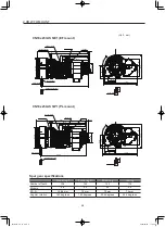
Page 14: ...tation 180 degrees 180 degrees 93 5 degrees 52 5 degrees 8 178 4 118 13 5 6 88 2 4 1 74 1 5 5 262 9 233 4 UNC1 4 20 11 䃥114 䃥17 68 125 2 1 96 4 2 1 91 7 Focus ring B Focus ring A Zoom ring Iris ring Lens holder 27 UNC3 8 16 Attachment holder 8 170 4 110 13 5 6 80 2 4 1 13 3 254 9 225 4 UNC1 4 20 11 70 2 125 68 䃥17 88 4 2 1 2 1 83 7 27 UNC3 8 16 Focus ring B Focus ring A Zoom ring Iris ring Lens ho...

Page 15: ... 2 13 141 3 111 5 101 5 4 1 10 3 5 6 2 1 256 2 UNIC1 4 20 5 5 φ54 38 131 7 57 1 117 2 186 7 44 2 58 8 69 5 72 9 58 9 4 5 φ114 11 φ17 Unic3 8 16 27 Focus ring B Focus ring A Zoom ring Iris ring Lens holder Attachment holder 8 274 1 191 2 13 133 3 103 5 93 5 4 1 10 3 5 6 2 1 248 2 UNIC1 4 20 13 3 φ54 38 131 7 57 1 117 2 186 7 44 2 58 8 69 5 72 9 58 9 4 5 φ114 Iris ring Focus ring B Focus ring A Zoom...

Page 16: ...mall screwdriver to set the level as desired To determine the maximum gain set the trimmer at a level where no hunting occurs 4 Put back the rubber cap after adjustment completes Iris Operation Mode Change over Switch Clockwise to increase gain Iris Gain Adjusting Trimmer Rubber Cap 3 2 IRIS GAIN ADJUSTMENT An iris gain adjusting trimmer is located on the front of the lens drive unit The iris gain...

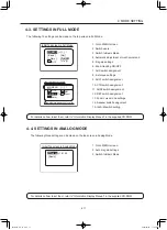
Page 17: ...in adjustment use either display or trimmer operations Shuttle shot frame preset speed preset and zoom tracking are not available This manual describes only the items that can be set on the TOP screen in each mode For details on how to set them refer to Information Display Manual in the supplied CD ROM 4 2 SETTINGS IN BASIC MODE The following nine settings can be made on the top screen in Basic Mo...

Page 18: ... 15 Iris A M switch setting I Gain Trk OFF MENU 1 A Fr1P Basic Adj Trk OFF I Tq H Initial Top screen in Full Mode Items that are displayed by scrolling Item that is not scrolled MENU 1 Norm AM Zoom Z M RET R A 2 Fr1P MENU IG 50 Basic Initial Top screen in Analog Mode 4 4 SETTINGS IN ANALOG MODE The following three settings can be made on the top screen in Analog Mode 1 Go to MENU screen 2 Auto iri...

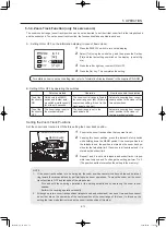
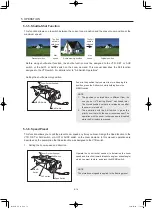
Page 19: ...AL REMOTE3 MANU SERVO MANU SERVO Zoom Operation Change over Knob Toward Telephoto end Toward Widest end Zoom Lever Zoom Ring 1 Set the zoom operation change over knob to SERVO position 2 Pressed the zoom rocker seesaw to perform zoom operation Zoom speed changes by the depth of the switch being pressed The deeper the switch is pressed the faster the zoom speed be comes IR IS RET AM I G T W Zoom Ro...

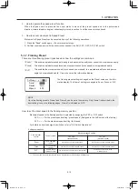
Page 20: ...et each setting item refer to Information Display Manual in the supplied CD ROM B Setting ON or OFF by operating the switches Selection method Operation How to ascertain the selection To set the function to ON Hold down the MEMO switch and Instant auto iris switch simultaneously for at least 3 seconds The zoom control range is fixed to the zoom range set last If there is no previous setting it is ...

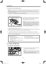
Page 21: ...om speed and direction toward telephoto angle or widest angle which you want to store and press the MEMO switch NOTE The stored zoom speed is applied to the framing preset Zoom Rocker Seesaw Shtl Switch Sped Switch Fr1P Switch MEMO Switch Present position Suttle memory position Original position The Shtl switch is held down The Shtl switch is released Max speed Max speed Setting the shuttle memory...

Page 22: ...n the memory Only Frame1 is described in the description given on the following pages Frame1 is indicated as Fr1P The zoom and focus are controlled in such a way that they start and stop simultaneously Control content Movement speed setting Frame preset control Setting combinations Zoom Z F Focus Fr1P Fr2P speed settable The zoom moves at the preset speed Zoom operation control Focus operation con...

Page 23: ...he position that you want to store while holding this zoom and zoom focus position press the Fr1P switch while holding down the MEMO switch NOTE This framing memory position is different from the shut tle memory position Refer to 5 1 5 Suttle Shot Func tion The stored zoom position remains in the memory even after the power is turned off 5 OPERATION Zoom Rocker Seesaw Shtl Switch Fr1P Switch MEMO ...

Page 24: ...d set the zoom operation change over knob to SERVO position 2 Mount the accessory such as focus demand For the details refer to the operation manual of accessories ZOOM FOCUS フォーカスサーボ マニュアル 切替えノブ Focus Operation Change over Knob REMOTE1 REMOTE2 VIRTUAL REMOTE3 MANU SERVO MANU SERVO 2 Turn the focus ring to bring the near or far object into fo cus 5 3 2 Manual Iris Operation Slide the iris operatio...

Page 25: ...ance becomes shorter than the normal minimum object distance M O D The minimum object distance by macro operation for this lens is CN7x17 10cm CN10x25 25cm from tip of the lens at the widest angle In macro shooting when zooming to change the focal length the focal point varies The multi point focus shooting technique uses this characteristic The focal point is shifted by the zoom op eration Follow...

Page 26: ...e function to be changed appears on the display 4 Press the Set key This completes the setting Switch Default value Functions Fr1P FRM2 Sped Shtl Sped Shtl NON RET VTR 1 V VTR 2 R RET 3 A Fr1P 4 A1 Shtl 5 A2 Fr1P 4 and 5 are AUX1 and AUX2 switches on the zoom demand Switch name Description VTR Starts stops VTR operation RET Hold down to view the main line video on the view finder Fr1P Fr2P Press t...

Page 27: ...he drive unit is mounted again mount it while referring to Section 6 2 6 1 HOW TO DETACH THE DRIVE UNIT 1 Turn the camera and the lens power off 2 Disconnect the 12 pin cable 3 Detach the lens body from the camera 4 Remove the three drive unit fixing screws 5 Insert the removed screws 3 into the specified screw holes 3 shown on the following seal in the lens body Docking screw caution seal Docking...

Page 28: ...e torque and with a pitch of 0 5 If the drive unit is removed the iris ring may turn and the iris position may change To retain the iris position mount a cinema operation accessory with adjustable torque and with a pitch of 0 4 on the iris ring For details on the operation accessory with a pitch of 0 4 contact Canon Inc or Canon distributers sales representatives 6 HOW TO ATTACH AND DETACH THE DRI...

Page 29: ...nit fixing screw holes in the lens body NOTE If the drive unit is fixed when there is a foreign mate rial in a screw hole the lens body may be damaged 4 Fit the connector of the drive unit into the connector of the lens using the positioning pin of the drive unit as a guide and while pushing the drive unit to the lens body fix them temporarily by lightly tightening the three fixing screws that wer...

Page 30: ...e turn each iris ring manu ally and check gear engagement 6 Verify that the gear of the drive unit is engaged with the gear of the lens and tighten the three fixing screws to the specified torque to fix the drive unit Tightening torque 63 80 N cm 6 4 8 2 kg cm 7 Mount the lens on the camera connect the 12 pin cable switch the power on and adjust the mechanical end au tomatically on the display For...

Page 31: ...he key 2 Press the key Adjustment begins The screen changes to the mechanical end adjustment screen 3 Press the key and press the key Initial top screen MENU Set Set Set Adj Adj is highlighted Trk OFF Shtl A 1 A 2 MENU IG 50 A Fr1P Fr1P I Tq H Adj Trk OFF Shtl A 1 A 2 IG 50 A Fr1P Fr1P I Tq H Lens AutoAdjust OK y n The screen flashes during adjustment Auto Adjustment Succeeded Lens Interface Conne...

Page 32: ...at M O D H V Wide angle end 86 3 48 4 cm 92 1 48 5 cm Telephoto end 12 0 6 7 cm 12 7 6 7 cm Front Diameter φ 114 mm Thread for filters φ 112 mm P1 Lens body φ 127 mm P0 75 In the hood Zoom speed for full range Max 0 5s 0 2s Focus speed for full range 1 6s 0 3s Power source DC12V DC10 17V Current consumption Max 500 mA Operating temperature Temperature 20 45 Humidity 5 RH to 95 RH no condensation W...

Page 33: ...r Object Dimensions at M O D H V wide angle end 86 5 48 5 cm 92 1 48 5 cm 89 3 47 1 cm 84 4 56 2 cm 57 7 32 3 cm 61 4 32 3 cm telephoto end 8 7 4 9 cm 9 3 4 9 cm 9 0 4 8 cm 8 5 5 7 cm 5 8 3 3 cm 6 2 3 3 cm Front Diameter φ 114 mm Thread for filters φ 112 mm P1 Lens body φ 127 mm P0 75 In the hood Focus speed for full range Max 0 5s 0 2s Focus speed for full range 1 6s 0 3s Power source DC12V DC10 ...

Page 34: ...n addition this tendency increases for lenses with longer focal lengths When shooting images carefully check the focusing condition using the zoom mode of the finder or other means and shoot a sufficient number of test images before performing focus operations for EF mount Lens only The T numbers of this lens are indicated on the iris ring of the lens On the other hand the iris information from th...

Page 35: ...資料集 TECHNICAL INFORMATION 资料汇编 BT1 B051 E_資料集_JEC indd 1 2020 02 13 15 28 19 ...

Page 36: ...BT1 B051 E_資料集_JEC indd 2 2020 02 13 15 28 20 ...

Page 37: ...TERNAL VIEW 外观图 1 CN7x17 KAS S P1 166 9 146 9 95 View A Unit mm 137 7 43 4 35 57 174 2 117 2 38 57 2 125 68 55 5 34 4 254 9 225 4 䃥114 指標線位置 Index Mark ḽ㓵փ㖤 13 3 A BT1 B051 E_資料集_JEC indd 1 2020 02 13 15 28 28 ...

Page 38: ...137 7 51 4 34 4 262 9 233 4 35 57 174 2 117 2 38 57 2 125 68 55 5 166 9 146 9 95 䃥114 View A Unit mm 5 5 A 指標線位置 Index Mark ḽ㓵փ㖤 2 CN7x17 KAS S E1 BT1 B051 E_資料集_JEC indd 2 2020 02 13 15 28 37 ...

Page 39: ...4 1 248 2 13 3 φ54 38 131 7 57 1 166 9 146 9 137 7 66 6 117 2 186 7 44 2 58 8 69 5 72 9 58 9 4 5 95 φ114 A 指標線位置 Index Mark 指标线位置 View A Unit mm 3 CN10x25 IAS S P1 BT1 B051 E_資料集_JEC indd 3 2020 02 13 15 28 41 ...

Page 40: ... 256 2 5 5 38 131 7 57 1 166 9 146 9 137 7 74 6 117 2 186 7 44 2 58 8 69 5 72 9 58 9 4 5 95 φ114 A 指標線位置 Index Mark 指标线位置 View A Unit mm 34 4 4 CN10x25 IAS S E1 BT1 B051 E_資料集_JEC indd 4 2020 02 13 15 28 43 ...

Page 41: ... フード 5 フォーカス 17 フランジバック 9 マクロ 18 INDEX BACK FOCUS E9 EXTENDER E18 FOCUS E17 HOOD E5 IRIS E17 MACRO E18 RET E19 VTR E19 ZOOM E12 索 引 RET C19 VTR C19 变焦 C12 光圈 C17 后焦 C9 聚焦 C17 扩展器 C18 趋近拍摄 C18 遮光罩 C5 BT1 B051 E_資料集_JEC indd 5 2020 02 13 15 28 44 ...

Page 42: ...anon U S A Inc http usa canon com support Tel BCTV 800 423 5367 USA Only Tel Cinema Lens 855 246 3367 USA Only ASIA CHINA 佳能 中国 有限公司 http www canon com cn supports service html 电话 86 0 10 8513 9999 JAPAN キヤノンマーケティングジャパン株式会社 http canon jp Tel 03 3740 3305 KOREA 캐논코리아컨슈머이미징 http www canon ci co kr SOUTH SOUTHEAST ASIA Canon Singapore Pte Ltd http www canon asia com bctv TAIWAN Canon Marketing Taiwan...

Page 43: ...会社 146 8501 東京都大田区下丸子 3 30 2 CANON INC 30 2 Shimomaruko 3 chome Ohta ku Tokyo 146 8501 Japan 修订 2020 2 1 Pub No BT1 B051 E 0420S 原产地 日本 2020 02 CANON INC BT1B051E BT1 B051 E_資料集_JEC indd 8 2020 02 13 15 28 44 ...

Reviews: