background image

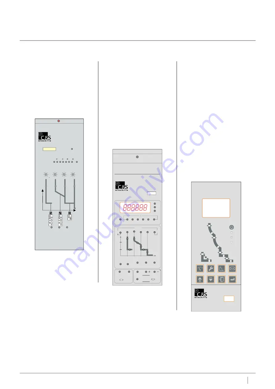
MicroPro2-3.1

MicroPro2-4.1

MicroPro2-7.1 

Release Type MicroPro2-3.1, 4.1 & 7.1 

LSIGN with additional protection - under Current, Current unbalance
under / over voltage, under/over Current, under/over Frequency & Earth Leakage

Measurement of True RMS value of current

Measurement of Current, Voltage, Frequency, Harmonics & Power parameters

Last fault Trip history

Zone selective interlocking

Digital display & fault LED retention

Zone selective interlocking

In-built thermal memory

1 or 2 way communication

Communication Protocol through Modbus-RS 485/232

Features

Micropro release is equipped with LCD display which is part of same navigator panel. 
Control unit is designed to offer great use for user to access and operate the same easily 
and without any training. 

Micropro is completely microprocessor based device with LCD display offering various 
options including ammeter, power measurement, zone selectivity, Neutral protection, 
diagnosis facilities and harmonics filter. These control units also offers communication 
through RS485 / Modbus protocol.

MicroPro2 3.1

Overload protection
Short Circuit current protection
Earth Fault protection
INST Fault protection

n

n

n

n

MicroPro2 4.1

Overload & Short Circuit protection
Instantaneous current protection
Neutral & Ground Fault Protection
Ampere Meter
Digital display and fault LED retention 

in  case of power failure

n

n

n

n

n

MicroPro2 7.1

Overload & Short Circuit protection
Instantaneous current protection
Neutral & Ground Fault / Leakage
Protection

Various Protection related to voltage,
frequency, load and motor

Zone Selectivity, Measurement of V, I,

P, F, KWH, KVArh, Harmonics etc.

Communication

Port: RS485
Protocol: Modbus/Profibus/Devicenet

n

n

n

n

n

n

n

and also store the maximum value in

maximeter

25

C&S Electric Limited

RESET

RESET

Warn/Alarm

Warn/Alarm

Healthy

Healthy

Comm.

Comm.

lg

lg

lr

lr

ls

ls

lsd

lsd

lili

TEST

micro

7.1

pro

RESET

micro 

2 - 4.1

pro

WM2 Intelligent Trip Unit

2000

In =

G

L

1

L

2

L

3

MAX.

MAX.

SELECT

A

kA

S

SET

LOAD1

LOAD2

lr

4

lr

1

lr

2

lr

3

A

check

Fault

clear

trip

S

t

l

t

S

t

G

nontrip

test

memory

adjust

DC24V

ti

RESET

micro 

2 - 3.1

pro

In=

2000A

MCU

%I

r

1

40

60

80

100

Load current

Overload

0.8

0.4

0.7

OFF

0.6

1.0

0.5

0.9

0.6

0.2

0.5

OFF

0.4

0.8

0.3

0.7

7

3

6

OFF

5

10

4

8

16

10

14

OFF

12

20

11

18

Ir

4

Ir

1

Ir

2

Ir

3

x

In

x

In

x

In

x

In

WM2 Intelligent Trip Unit

Troubleshooting

Test

Reset

t

I

t

G

t

L

ts

0.2S
0.4S
0.6S
0.8S

30S
60S
120S
240S

0.2S
0.4S

Intelligent trip units

Intelligent trip units

24

C&S Electric Limited

W Nmaster 2

i

W Nmaster 2

i

and also store max. value in maximeter

Summary of Contents for WiNmaster 2

Page 1: ...Air Circuit Breaker Ro S H Compliant W Nmaster 2 i 630A 3200A www cselectric co in ...

Page 2: ... to 3200 Amp in two basic frames with fault interruption ratings of up to 65kA A design offering a unique combination of High Fault current withstands ratings short fault interruption time and zone selectivity The device includes the new state of the art MicroPro2 intelligent trip unit that enables the circuit breaker with the latest technology for system safety reliability measurement relaying an...

Page 3: ......

Page 4: ...eristics 16 17 Connection Installation 18 19 External Configuration 20 21 Intelligent Trip Units 22 35 Characteristic Curves 36 47 Communication 48 ZSI micropro2 49 Accessories 50 53 Electrical Diagram 54 55 Identifying ACB 56 57 Dimensions 58 60 5 C S Electric Limited C S Electric Ltd W Nmaster2 i ...

Page 5: ...6 C S Electric Limited Complete Modular construction ...

Page 6: ...e protective coordination and electric power monitoring system WiNmaster 2 has a modular construction which has been designed according to customer sdemand and present day complex requirement of electrical systems These ACBs are most compact in size with wide range high breaking capacity Compact yet offering Horizontal Type Busbar Termination for ease of installation enhanced life and intuitive op...

Page 7: ...Fixed Type Drawout Type 8 C S Electric Limited Available in both Fixed Drawout version ...

Page 8: ...rame WX A up to 2500A The panel cutout size is same for all types of W Nmaster2 which makes it easy to arrange them in switchboards Panel cutout for front remains same i The sheet steel structure of WiNmaster 2 is extremely compact considerably reducing overall dimensions W Nmaster 2 circuit breakers comes in two frame sizes WX A 630A to 2500A WX B 2000A to 3200A i 9 C S Electric Limited Structure...

Page 9: ...at are installed on a contact support One end of contacting piece of the contact is connected with the busbar through flexible connection When the circuit breaker closes the main shaft drives the connecting rod to make the contact support revolve around the point A counterclockwise after the moving contact touches the static contact the contact support will continue to rotate around the point A co...

Page 10: ...ished it is ready for closing of circuit breaker Closing Press the closing button or closing electromagnet let the half shaft of energy releasing release rotate counterclockwise then the lever 1 pressing against the energy releasing tripping half shaft trips cam rotates clockwise under the action of energy storage spring force until reaching the cam gap energy storage lever rotates counterclockwis...

Page 11: ... breakers are available in Drawout fixed versions The drawout version is mounted on a chassis the fixed version is installed using fixing brackets i Drawout version Fixed version 12 C S Electric Limited Constructions Characteristics W Nmaster2 i ...

Page 12: ...Chassis Circuit breaker Front cover 13 C S Electric Limited Constructions Characteristics W Nmaster2 i ...

Page 13: ...RoHS Compliant 14 C S Electric Limited ...

Page 14: ...ng energy losses insignificant the materials are marked to facilitate sorting for recycling at the end of product service life i n n n Conformity to RoHS Directive C e ompliance with nvironmental requirements RoHS Compliant WiNmaster2 ACB is a product confirming to RoHS Restriction of Hazardous Substances directive That means in conformity with EU Directive Lead Pb Cadmium Cd Mercury Hg Hexavalent...

Page 15: ......

Page 16: ......

Page 17: ...18 C S Electric Limited Mixed type Vertical type Horizontal type Cradle terminal as per panel manufacturer ...

Page 18: ...ar as product is available with horizontal terminal requirement meeting varied customer requirement for termination Such facility allows user to optimize the size of switchboards and busbar connection W Nmaster2 ACB provides you total solutions with an advanced trip relay for measurement diagnosis analysis and communication as well as protective functions for absolute protective co ordination and ...

Page 19: ...late Charge Discharge indicator Front facia Auxiliary terminal shield 2 3 1 4 5 6 7 8 8 5 7 2 3 6 1 Auxiliary Contact group Arc chute Switch Body Intelligent release Spring charging motor Electric motor Charging handle Closing coil Shunt coil UVT UVT Delay block 2 3 1 4 5 6 7 8 9 10 11 1 2 4 9 9 3 20 C S Electric Limited 4 5 6 7 8 9 10 11 W Nmaster2 i ...

Page 20: ...ving the top cover of ACB and all accessories are clip on require no screws for mounting and even motor drive require just one screw for mounting on the ACB for easy access E I o m ase of nstallation peration and aintenance Charging handle Operational position indication UVT Delay Block Closing coil Shunt coil UVT coil Spring Charging Motor Pad Lock position Auxiliary terminal shield Auxiliary ter...

Page 21: ...round fault It supports the advanced measurement functions for voltage current power electric energy harmonics communication function and others Analog trip function interlock with mechanism enhanced a durability of devices as well as the breaking capacity of ACB Zone selective interlocking function make the protective coordination more simple and thermal memory can be applied to various loads 22 ...

Page 22: ... changeover contacts determine its working position according to the state of magnetic flux converter Body case In the body case there is a basic circuit board of release which receives various signals and sends out various commands according to the preset functions and requirements after judgment to finish the functions required by circuit breaker Sensor The sensor is installed on the main circui...

Page 23: ... 1 or 2 way communication Communication Protocol through Modbus RS 485 232 Features Micropro release is equipped with LCD display which is part of same navigator panel Control unit is designed to offer great use for user to access and operate the same easily and without any training Micropro is completely microprocessor based device with LCD display offering various options including ammeter power...

Page 24: ...485 Protocol Modbus Profibus Devicenet n n n n n n n and also store the maximum value in maximeter 25 C S Electric Limited RESET RESET Warn Alarm Warn Alarm Healthy Healthy Comm Comm lg lg lr lr ls ls lsd lsd li li TEST micro 7 1 pro2 RESET micro 2 4 1 pro WM2 Intelligent Trip Unit 2000 In G L1 L2 L3 MAX MAX SELECT A kA S SET LOAD1 LOAD2 lr4 lr1 lr2 lr3 A check Fault clear trip S tl tS tG nontrip ...

Page 25: ......

Page 26: ... Practice cable current characteristics of the neutral phase is very different from that of the other three phases Micropro 2 7 1 take different protection measures according to different application needs When the cable is relatively thin half the set value can be used and when the cable is normal the set value can be used When the mains harmonics are relatively big double value Earth fault prote...

Page 27: ... recorded in to 3 separate files that may be displayed on screen Tripping history Type of faultb Date time Values measured at the time of tripping Alarm histories Type of fault Date time Values measured at the time of alarm ACB status It will give information about the ACB tripping locally or remotely etc Maintenance indicators Micropro2 7 1 gives information about the maintenance parameters of AC...

Page 28: ...Curve Multiple Cr 1 5 6 OFF Delay Tg 0 1 1S Earth Leakage Protection I n Δ 0 5 30 0A Delay Set Value 0 1 40 0S Earth Leakage Delay Time TΔn S Instantaneous 0 06 0 08 0 17 0 25 0 33 0 42 0 5 0 58 0 67 0 75 0 83 Current Unbalance Protection 5 60 Return Value 5 Start Value Return Delay 10 200S Performance Alarm Break Close Protection Start Set Value 100V Return Value Protection Delay Return Time 0 2 ...

Page 29: ...controller without connecting port output Alarm trip close Performing way Set value of the protected Starting Return value 1200V Delay time of protection returns 0 2 60S Over Voltage Protection Parameters Delay time set of the protected operation 0 2 60S Set value of the protected operation returns Start Value 1200V Protect alarming DO output Set one DO of the signal units as overvoltage error not...

Page 30: ...not set this item the alarm infor can be only read from the screen of the controller without connecting port output Alarm trip close Performing way Current Setting of Alarm Action 0 5 30 0A Alarm Action Time Delay 0 0 1 0S Leakage Alarm Alarm Return Current Setting 0 5 30 0A Alarm Return Delay 0 0 1 0S Alarm DO Output Set one DO of the signal unit as Leakage Alarm Alarm Switch Off Performance Dela...

Page 31: ...ing indicator Short circuit current of the short time delay Short circuit prtection short delay time setting indicator Short circuit current instantaneous protection and alarm indicator Troubleshooting button Spare key Load monitoring and alarm indicator 2 current set Set the value of the reduced bond Set the value of the increased bond Panel power jack Setting storage switch Storage indicator Do ...

Page 32: ...F 2 l t on I 8Ir tsd s 0 1 0 2 0 3 0 4 t 2 8lr tsd 2 l Time setting Instantaneous li li lnx Pick up A 1 50kA OFF Instantaneous Time setting Time delay ms Accuracy 40ms Earth fault lg tg s 0 1 0 2 0 3 0 4 lg In x Pick up A 0 2 1 OFF tg s 0 1 0 2 0 4 OFF Min ms Max ms 60 160 255 340 140 240 345 460 Indication Monitoring Control Power On Led indicator Overload LED indicator Overload trip LED indicato...

Page 33: ...t of the short time delay setting coding switch Short circuit current coding switch transient protection Short circuit transient protection fault indicator Short time delay short circuit fault indicator Long delay overload protection fault indicator Grounding protection fault indicator Short circuit protection short delay time stubbs switch setting Overload protection long delay time setting slide...

Page 34: ... 16 18 20 0FF Instantaneous 1 5 x lr 30 60 120 240 tg s 30 60 120 240 2 x lr 7 2 x lr 16 9 33 8 67 5 135 1 3 2 6 5 2 10 4 Indication Monitoring Control Power On Led Indicator Overload LED indicator Overload trip LED indicator Short circuit trip LED indicator Earth Fault trip LED indicator Earlier terminology Long time lr1 Short Time lr2 Instantaneous lr3 Earth fault lr4 30 min Optional tsd s 0 2 0...

Page 35: ......

Page 36: ...Micropro 2 3 1 Micropro 2 4 1 37 C S Electric Limited Characteristics Curve W Nmaster2 i ...

Page 37: ...Chart A3 Very inverse time lag Ir long delay set value Chart A2 Standard inverse time lag Ir long delay set value Micropro 2 7 1 38 C S Electric Limited Characteristics Curve W Nmaster2 i ...

Page 38: ...ime lag distributing protection Ir long delay set value Chart A5 Extremely inverse time lag generator protection Ir long delay set value tripping time secs Micropro 2 7 1 39 C S Electric Limited Characteristics Curve W Nmaster2 i ...

Page 39: ...ltage fuse compatible Ir long delay set value tripping time secs Chart A7 Extreme inverse time curve Ir long delay set value tripping time secs Micropro 2 7 1 40 C S Electric Limited Characteristics Curve W Nmaster2 i ...

Page 40: ...erse time lag standard reverse time lag Ir long delay set value Chart S2 Sort time delay reverse time lag fast reverse time lag Ir long delay set value Micropro 2 7 1 41 C S Electric Limited Characteristics Curve W Nmaster2 i ...

Page 41: ... reverse time lag distributing protection Ir long delay set value Chart S4 Sort delay reverse time lag express reverse time lag generator protection Ir long delay set value Micropro 2 7 1 42 C S Electric Limited Characteristics Curve W Nmaster2 i ...

Page 42: ...se time lag high voltage fuse compatible Ir long delay set value Chart S6 Short time reverse time lag common use reverse time lag Ir long delay set value Micropro 2 7 1 43 C S Electric Limited Characteristics Curve W Nmaster2 i ...

Page 43: ...lue below Curve type fast reverse time lag Curve speed C1 C8 and C16 Operation set value of short delay reverse time lag 3 x Iset Delay time of short delay fixed time lag set value 0 3 S Ir long delay set value Micropro 2 7 1 44 C S Electric Limited Characteristics Curve W Nmaster2 i ...

Page 44: ...g delay set value The curve above bases on the fixed value below Delay time of short delay fixed time lag set value 6 x Ir Delay time of short delay fixed time lag set value 0 3 S Micropro 2 7 1 45 C S Electric Limited Characteristics Curve W Nmaster2 i ...

Page 45: ...elow Curve type fast reverse time lag Curve speed C1 C8 and C16 C1 fastest Operation set value of short delay reverse time lag 3 x Iset Operating set value of short delay fixed time lag 6 x Ir Delay time of short delay fixed time lag set value 0 3 S Micropro 2 7 1 46 C S Electric Limited Characteristics Curve W Nmaster2 i ...

Page 46: ...Chart G1 Creepage protection Chart G1 Ground protection Micropro 2 7 1 47 C S Electric Limited Characteristics Curve W Nmaster2 i ...

Page 47: ...0 bps 19200 bps 38400 bps Transmission Method Half duplex Termination 100 Modbus RS 485 n n n n n n n n Profibus DP Module is installed separately optional Operation Mode Differential Distance 1 2 km Cable Profibus DP Shielded twist 2 pair cable Baud rate 9600 bps 12Mbps Transmission Method Half duplex Termination 100 Standard EN 50170 DIN19245 Profibus DP ...

Page 48: ...time delay for protective coordination in the system However upstream breaker that did not receive its signal will trip instantaneously Fpor ordinary ZSI operations it should arrange operation time accordingly so that downstream breaker will react before upstream ones under overcurrent short time delay ground fault situations ZSI connecting lines need to be Max 3m n n n n n 1 Occurrence of fault A...

Page 49: ...50 C S Electric Limited n n n Spring charging motor Opening closing coil Under voltage release Snap in type Accessories ...

Page 50: ...51 C S Electric Limited ...

Page 51: ...antaneous Operating voltage value of release 35 70 Ue It is able to open the circuit breaker 35 Ue Circuit breaker is unable to close 85 110 Ue Circuit breaker is able to close reliably Within of delay time when the source voltage recovers to 85 Ue Note Accuracy of delay time is 10 Auxiliaries for remote operation 52 C S Electric Limited Opening release closing release Basic Function Opening relea...

Page 52: ...terlocking can be achieved by using 2 locks with 1 key 3 locks with 2 keys n n The key lock inhibits local remote closing of circuit breaker Door Interlock Basic Function Connected or Test position It may be mounted on the left or right hand side of the chassis n n This device inhibits opening of the cubicle door when the circuit breaker is in Auxiliary Terminal Shield Basic Function This shield p...

Page 53: ...Micropro 2 3 1 Micropro 2 4 1 Micropro 2 7 1 54 C S Electric Limited Electrical Diagram Micropro 2 3 1 W Nmaster2 i ...

Page 54: ...Identifying Electrical Auxiliaries Electrical Diagram 55 C S Electric Limited Electrical Diagram additional features W Nmaster2 i ...

Page 55: ...Model Description Identifying WX ACB 56 C S Electric Limited W Nmaster2 i 25 2500A 32 3200A H 65kA A Basic Releasse 3P N 3 Pole Neutral W Nmaster2 i ...

Page 56: ... c u i t b r e a k e r wi t h a c c e s s o r i e s Rating W Nmaster 2 WX series Intelligent Circuit Breaker offer current ratings from 630A to 2500A The new generation intelligent controller provided basic protection of distribution network with specialized function like Measurement Maintenance and Man Machine interface i W Nmaster2 i IEC 60947 2 CEI EN 60947 2 IS 13947 2 Utilisation Category B A...

Page 57: ...n n n n n n Draw out type 630 2500A 3P 4P Fixed type 3200A 3P 4P Draw out type 3200A 3P 4P Fixed type Panel cutout dimension Draw out type Panel cutout dimension Fixed type 630 2500A 3P 4P Dimensions ...

Page 58: ...Dimensions Draw out type 630 2500A 3P 4P Fixed type 630 2500A 3P 4P 59 C S Electric Limited W Nmaster2 i Fixed type 3200A 3P 4P ...

Page 59: ...ype 3200A 3P 4P W Nmaster2 i Fixed type Panel cutout dimension Draw out type Panel cutout dimension Inm a b c d e 630 200A 306 172 5 345 132 5 170 mm Drawout Type Fixed Type to Insulator to Metal A B 100 30 A B 100 70 3200A 362 202 5 405 167 5 200 ...

Page 60: ......

Page 61: ... E R 2 0 1 0 1 2 0 1 5 C S Electric Ltd 222 Okhla Industrial Estate Phase III New Delhi 110020 INDIA Tel 91 11 3088 7520 29 Fax 91 11 26838291 2684 8241 E mail cmo cselectric co in www cselectric co in W Nmaster 2 i ...

Reviews: