


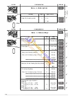


5
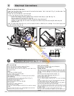
1.- Steel chassis complete with expansion vessel
2.- Sealed chamber
3.- Burner and heat exchanger assembly
4.- Air / gas connection
5.- 24 V modulating fan
6.- Gas valve
7.- Ignition electrode
8.- Ionisation probe
9.- Ignitor
10.- Combustion products manifold
11.- 24 V transformer
12.- Siphon
13.- Electrical box
14.- Pump
15.-
Shunt plate
16.- Pressure gauge
18.- Automatic air separator and automatic vent
19 - Central heating flowswitch
21.- Central heating control thermistor
23.- Overheat sensor
42.- Silencer
1
2
3
4
5
6
8
11
12
13
14
35
30 24
34
1
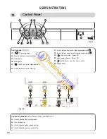
INSTALLER’S INSTRUCTIONS
7
Fig. 1
Fig 3
15
21
10
9
Fig. 2
33
36
31
32
19
18
23
16
29
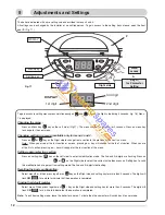
24.- Display
27.- Setting key
28.- Setting key
29.- Central Heating switch
30.- Green indicator – Central Heating mode ON
31.- Central Heating temperature reducing key
32.- Central Heating temperature increasing key
33.- Green indicator – Power ON
34.- Orange indicator - Burner ON
35.- Red indicator - Lock out / flame failure
36.- Reset key
27
28
42
Description