


Higher mV/div scope settings (sensitivity) can also be used, but this will result in a
less precise P/Z matching adjustment. Most scopes will overload for a 10 V input sig-
nal and will exhibit overload aftereffects when the signal returns to the baseline. Thus
the P/Z matching will be incorrectly adjusted resulting in a loss of resolution at high
count rates.
To prevent scope overload and increase the P/Z matching accuracy, a clamping circuit
such as the Canberra Model LB1502 Schottky Clamp Box should be connected at the
scope input.
P/Z Matching Using a Ge Detector and
60
Co
1.
Adjust the radiation source count rate to be between 2 kcps and 20 kcps.
Observe the trapezoidal waveform on the monitor output.
2.
Verify that the preamp type in the filter device MID editor is set to “RC”.
Adjust the Pole/Zero slider bar, located in the Filter Device Adjust screen, so
that the trailing edge of the trapezoid pulse returns to the baseline with no
overshoots or undershoots.
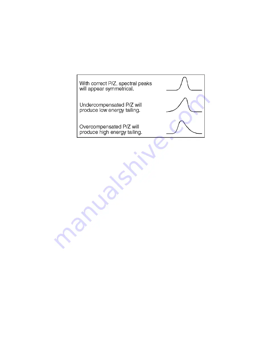
Figure 21 shows the correct setting of the P/Z adjustment, while Figures 22 and 23
show under- and over-compensation for the preamplifier decay time constant. As
illustrated for correct P/Z compensation, the monitor output signal should have a clean
return to the baseline with no bumps, overshoots or undershoots.
Note
Some systems may exhibit small undershoots when the monitor output returns
to baseline. These arise primarily from secondary time constants associated
with the detector/preamp system. If an undershoot is present and is less than
20 mV, its impact on performance is insignificant. However, if small under-
shoots are present, they should not be confused with undershoots caused by
Chapter 6 - Setup and Operation
42
Model 9660-9660A ICB Digital Signal Processor
Figure 20 Pole/Zero Compensation - Examples


