Integrating the MDT SMART Link-485
4
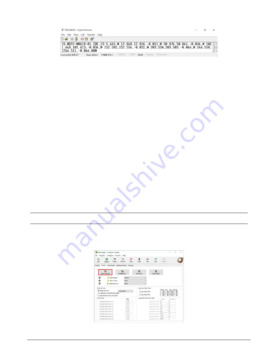
(Figure 7 - Response from SMART Link-485)
The fields of the string in Figure 7 are as follows:
"S"
- start of the sample/string/response.
"MDTC-M0618-01" -
the serial number of the extensometer connected to the SMART Link-485.
"IDE
" - indicates the location where the information about the MPBX was read from. The "E" indicates the
SMART ID is
external
to the Link-485, this is usually the case when using SMART Link-485.
If this had been "IDI", the "I" standing for "internal" would indicate that the information about the
MPBX was read from within the Link-485 (an extra SMART ID is added inside the Link-485). This
would be the case when the Link-485 is paired/bonded to a specific legacy instrument that does not
have a SMART ID memory chip built in. The Link-485 would have the serial number of the MPBX
penciled in on the label under the "Paired SMART Instrument SN".
"23.5"
- temperature in Celsius
"645"
- this is a legacy value for Voltage that MDT has kept for backwards compatibility issues. This value
divided by 56 gives you volts DC. In the example 645/56 =11.5Vdc.
"M"
- precedes the first reading (position) and indicates Metric units.
Three values following “M”
- first value is the
initial value
, the second value is the
current reading
(this
is the value that will be reported in MultiLogger
) and the third value is the
delta
. There are as many of
these 3 value entries as there are sensors on the SMART Link-485 (in the example there are six).
"AAM" -
echo of the port, channel and unit command issued: All ports, All channels, Metric units.
MultiLogger Configuration
Typically, the
Direct Connect Channel
configuration would be used for configuring the SMART Link-485.
However, since the number of Direct Connect Channels in a Campbell CR6 Datalogger are limited to 12 and
each position requires a channel; if the system must read more than 2 MPBXs with 6 positions each, there
would be insufficient channels. In this case, use a
Multiplexer
configuration, the following section details this
configuration.
Note - A gage type has been added to support reading the MDT SMART Link-485. Contact Canary Systems
if your
installation of software does not list the required gage types.
Direct Connect Channel Configuration
Add a Campbell CR6 MCU to the network, double-click to load the Logger form. Then, select the
Direct
Connect
option on the
Program
tab, as shown in Figure 8.
(Figure 8 - Program tab of the MultiLogger
program configuration outlining the Direct Connect option)


