
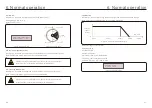


8. Troubleshooting
.68.
.69.
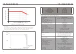
9. Specifications
Model
Dimensions (W*H*D)
Weight
942*733*311 (mm) / 37.1*28.9*12.2 (inch)
84kg / 185.2lb
3/PE~600
Max. DC input voltage (Volts)
MPPT voltage range (Volts)
Max. input current (Amps)
MPPT number/Max input strings number
Rated grid voltage (Volts)
Max. output current (Amps)
Power Factor (at rated output power)
Max.efficiency
EU efficiency
Topology
Self consumption (night)
Operating ambient temperature range
Relative humidity
Ingress protection
Noise emission
Cooling concept
Max.operation altitude
AC connection
Compliance
DC connection
1500
150
300
1/1
0.8leading~0.8lagging
60
59.5-60.5
99.1%
98.6%
Transformerless
<
3W (without anti-PID)
-13
℉
~140
℉
(-25
℃
~60
℃
)
0~100%
Type 4X
≤
65dB(A)
Intelligent redundant cooling
13120ft / 4000m
Display
Communication connections
Warranty
Rated output power (Watts)
Max. output power (Watts)
Max. apparent output power (VA)
LCD, 2x20 Z
RS485, Ethernet, Optional: PLC
10 years (extend to 20 years)
950
125000
125000
125000
120
THDi (at rated output power)
<3%
Start-up voltage (Volts)
Max short circuit input current (Amps)
Rated DC voltage (Volts)
Rated grid frequency (Hertz)
Grid frequency range (Hertz)
860...1450
900
UL 1741, UL 1741SA, Rule 21, UL 1998,
IEEE 1547, FCC Part 15 (Class A & B),
CAN/CSA C22.2 107.1-16, Rule 21 Phaes II&III
OT Terminal connectors(Max.185mm²)
OT Terminal connectors(Max.185mm²)
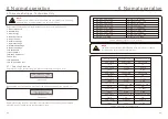
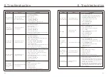
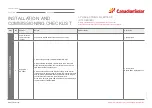
Alarms
Cause
Solution
• Inverter detects grid
instability, internal fault
current high
GRID-INTF:
Grid unstable
Test – With DC Switch OFF
• Measure AC voltage
• Test AC line for THD
• Test – With DC Switch ON
Test AC line for THD
• Multiple inverters/turn one off
• Impedance matching adjustment or box
• Internal damage
• Wire came loose in shipping
INI-PRO:
Initialization
Protection
• Master and Slave DSP
have different values
Reset Inverter
• DC switch OFF
• Wait until all lights/LCD turn off
• DC switch ON
• Replace inverter
TEM-PRO:
Temperature
Protection
• Inverter detects high
ambient temperature >60C
Inspect installation
• Check heatsink for obstructions/ventilation
• Is inverter in direct sunshine
• Measure ambient temperature near inverter
• If temp is in range replace inverter
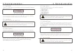
Table 8.1 Fault messages and descriptions
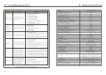
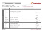
PV ISO
PRO 01/02
• Inverter detects low DC
insulation resistance on
the PV+ or PV- terminals
Inspect installation
• Restart inverter
• Note weather conditions when alarm occurs
• Measure insulation resistance
• If normal, measure in SAME weather as alarm
• Physically check cables
Reve-DC
•
Please check the inverters’ PV string polarity,
if there are strings reversely connected wait for
the night when the solar irradiance is low and the
PV string current down below 0.5A. Turn off the
two DC switchs and fix the polarity issue.
If string polarity is correct, please confirm that all
•
the PV strings have the same number of modules.
If not, please modify the system configuration.
• One of the DC string is
reversely connected
• OR different number of
modules are connected
to the string inputs
(Threshold varies between
different conditions)
PV-MID-ISO
• Inverter detects low DC
insulation resistance on
the middle connections
of the PV strings
(ie, MC4 connectors
between modules)
Inspect installation
• Restart inverter
• Physically check the all the MC4 connectors,
external DC switch, DC fuses.
CSI-125K-T600GL02-U


