


5. Commissioning
3). Measure the voltage present between the positive and negative wires of each string.
If the open circuit voltage of the string is near the maximum value accepted by the
inverter, verify the string length. Low ambient temperatures cause an increase in
the string voltage causing potential damage to the inverter.
4). Check the polarity of the string. All digital meters have a negative (“-“) indicator that
indicates when a voltage is negative; in this case a string connected in reverse
polarity.
WARNING
Input voltages higher than the maximum value accepted by the inverter
(see “Specifications” in Section 9) may damage the inverter.
Although Canadian Solar inverters feature reverse polarity protection,
prolonged connection in reverse polarity may damage these protection
circuits and/or the inverter.
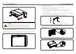
5.4.3.2 Leakage to ground
5.4.3.2.1 Detection of leakage to ground
Canadian Solar inverters are transformer-less and do not have an array connection to ground.
Any measurement of a fixed voltage between ground and either the positive or negative string
wiring indicates a leakage (ground fault) to ground and must be corrected prior to energizing
the inverter or damage to the inverter may result.
To measure leakage to ground, perform the following steps:
1). Ensure that all fuse holders are open.
2). Ensure that neither negative nor positive DC conductors are connected to the ground
strip.
3). Measure each string positive connection to ground.
4). Measure each string negative connection to ground.
5). Verify the voltage is “floating”, not a consistent voltage to ground. Make sure you notice
the units of the measurement. mV is not the same as V.
6). Do not close the fuse holder and connect the strings if a leakage to ground has been
detected. Improper operation and damage to the inverter may result.
Once all DC tests have been completed, close the fuse holders.
Measure leakage to ground to check for a DC ground fault.
5. Commissioning
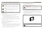
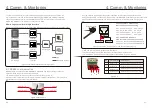
5.4 Preliminary checks
Verify DC connections.
1). Lightly tug on each DC cable to ensure it is fully captured in the terminal.
2). Visually check for any stray strands that may not be inserted in the terminal.
3). Check to ensure the terminal screws are the correct torque.
WARNING
High Voltage.
AC and DC measurements should be made only by qualified personnel.
5.4.1 DC Connections
Verify AC connections.
1). Lightly tug on each AC cable to ensure it is fully captured in the terminal.
2). Visually check for any stray strands that may not be inserted in the terminal.
3). Check to ensure the terminal screws are the correct torque.
5.4.2 AC Connections
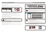
5.4.3 DC configuration
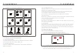
5.4.3.1 VOC and Polarity
To measure the open circuit voltage (VOC) and polarity of the individual strings, perform
the following steps:
5.4.3.1.1 Check string voltage
1). Ensure that all fuse holders are open.
2). Connect the positive lead of the meter to the positive string cable of the string under
test. Connect the negative lead of the meter to the negative string cable of the
string under test.
WARNING
When the fuse holders are closed, parallel strings on the same MPPT are
connected together. If there is a voltage difference between the parallel
strings such as different string lengths, current will flow between the
parallel strings. Opening and closing the fuse holder in this instance is the
same as opening and closing under load. Damage to equipment and /or
injury to personnel may occur.
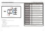
Verify DC configuration by noting the number of panels in a string and the string voltage.
Measure VOC, and check string polarity. Ensure both are correct and VOC is in specification.
.35.
.34.


