9
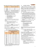
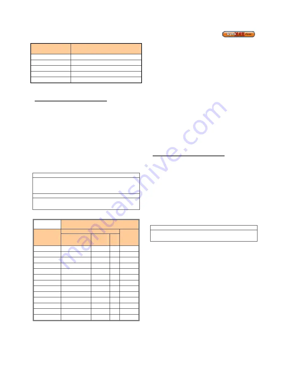
Table 6: Maximum Flue Temperature for Various Vent Materials
Vent Material
Maximum Flue Temperature [
o
F]
PVC
149
CPVC
194
PPE
230
AL29-4C
300+, limited only by rating of seals
316L Stainless Steel
300+, limited only by rating of seals
Stack temperature is typically between 15-30
o
F above inlet
water temperature depending on model size and firing rate.
Air Inlet (Supply Air or Fresh Air) Piping
•
PVC
•
CPVC (Chlorinated Polyvinyl Chloride)
•
PPE (Polypropylene)
•
ABS (Acrylonitrile-Butadiene-Styrene)
•
Single wall, Galvanized
•
Single wall, Stainless steel
•
Single wall, Aluminium
Single wall air inlet pipes are to be insulated 5 feet from the
wall toward the interior of the building to minimize external
sweating.
The following air intake options shall be utilized:
•
Outside air sealed direct (vertical or horizontal)
•
Outside air ducted to jacket flange
•
Indoor Air
NOTE
For wall hung units that are installed outdoors the bottom of
the unit must be at least 36” above ground or 12” above
normal snow levels.
NOTE
Sealed combustion is required when DynaMax HS is placed
in a space with other fan-assisted appliances.
Table 7: Required Vent and Air Inlet Diameters
Equivalent Length of Vent & Air Intake Pipes
at Recommended Diameter*
Model
Category IV
Category
II
Over 25' and up
to 100'
Over 15'
and up
to 25'
Up
to
15'
80
3"
3"
2"
-
100
3"
3"
2"
-
150
3"
3"
2"
-
200
3"
3"
2"
-
210
3"
3"
2"
4”
250
3"
3"
2"
-
260
3"
3"
2"
4”
299
4"
3"
3"
5”
399
4"
3"
3"
5”
500
4"
3"
3"
6”
600
4”
3”
3”
6”
700
4” (Air), 5” (Vent)
4”
4”
7”
800
5” (Air), 6” (Vent)
5”
5”
7”
* Consult factory for recommendations applicable to venting
combinations not shown above.
2.3
CATEGORY II VENTING
A category II appliance may be combined into a common
negative pressure venting system designed to ASHRAE
requirements using a proven vent sizing program. Vent
designs are to be certified by a qualified professional
designer acceptable to the authority having jurisdiction.
1)
The DynaMax HS Floor Mount boiler may be vented as a
Category II appliance using sealed vent suitable for a
condensing appliance.
2.3.1
Approved Venting Materials Category II
1) PVC and CPVC Schedule 40 approved to ULC S636.
2) Manufactured prefabricated UL/ULC listed vent of AL29-
4C or 316L stainless steel. Use of 316L is limited to use
where there is no possibility of contaminants in the air
such as refrigerants, chlorine etc.
3) PVC-DWV approved to comply with ANSI/ASTM D2665
(US Jurisdictions ONLY when permitted).
4) PVC Schedule 40 approved to comply with ANSI/ASTM
D1785. (US Jurisdictions ONLY when permitted)
5) CPVC Schedule 40 approved to comply with
ANSI/ASTM F441. (US Jurisdictions ONLY when
permitted).
6) Polypropylene approved to comply with ULC S636
Air Inlet (Supply Air or Fresh Air) Piping
•
PVC
•
CPVC (Chlorinated Polyvinyl Chloride)
•
ABS (Acrylonitrile-Butadiene-Styrene)
•
PPE (Polypropylene)
•
Single wall, Galvanized
•
Single wall, Stainless steel
•
Single wall, Aluminium
Single wall air inlet pipes are to be insulated 5 feet from the
wall toward the interior of the building to minimize external
sweating.
The following air intake options shall be utilized:
•
Outside air sealed direct (vertical or horizontal)
•
Outside air ducted to jacket flange
•
Indoor Air
NOTE
Sealed combustion is required when DynaMax HS is placed
in a space with other fan-assisted appliances.
2.4
COMBINED COMBUSTION AIR INLET
To avoid the possibility of nuisance lockouts in cold climates
install DynaMax HS appliances may be installed with a
combined combustion air inlet.
The combined combustion air inlet pipe sizing can be
calculated using the method shown below:
Equivalent pipe diameter = Sq Root [(d
1
)
2
+ (d
2
)
2
+ (d
3
)
2
+ …
+ (d
n
)
2
], where d
n
= individual pipe diameter
•
Example: Find the equivalent pipe diameter of three
air inlet pipes, 3” (7.6cm), 3” (7.6cm) and 4”
(10.2cm)
Equivalent pipe diameter = Sq Root[(3)
2
+ (3)
2
+
(4)
2
] = Sq Root(34) = 5.8”, select 6” (15.3cm)
equivalent diameter pipe.
Summary of Contents for DynaMax DMH081
Page 2: ......
Page 68: ...65 PART 14 EXPLODED VIEW PARTS LIST DYNAMAX HS WALL HUNG...
Page 69: ...66 DYNAMAX HS FLOOR MOUNT...
Page 76: ...73 PART 15 ELECTRICAL DIAGRAMS 15 1 DM 80 299 INTERNAL WIRING DIAGRAM...
Page 77: ...74 15 2 DM 399 800 INTERNAL WIRING DIAGRAM...
Page 78: ...75...

