10
Air inlet point for multiple boiler air inlets must be provided
with an exterior opening which has a free area equal to or
greater than the total area of all air inlet pipes connected to
the common air inlet. This exterior opening for combustion
air must connect directly to the outdoors. The total length of
the combined air inlet pipe must not exceed a maximum of
100 equivalent feet (30.5m). Compensate for the restriction
in an area provided by any screens, grills or louvers installed
in the common air inlet point. Screens, grills or louvers
installed in the common air inlet can reduce the free area of
the opening from 25 to 75% based on the materials used.
Increase the inlet accordingly.
2.5
VENT TERMINATION AND AIR INLET
CLEARANCES
2.5.1
Sidewall Venting
•
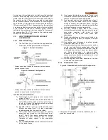
The first 3 feet (1m) of vent from the appliance flue
outlet must be readily accessible for inspection.
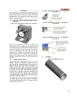
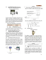
Figure 7: Vertical Orientation
* Always check local codes for minimum distance above
ground or snow levels
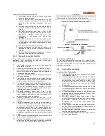
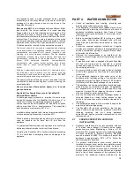
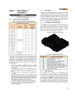
Figure 8: Horizontal Configuration
* Always check local codes for minimum distance above
ground (or snow levels in cold climates)
Location of Vent Termination
1) Total length of vent piping must not exceed limits
stated in Table 7.
2) Bottom of vent terminal shall be located at least 3
feet (0.90m) above grade or above normal snow
levels. In all cases the appliance shall be installed
in accordance with local codes
3) DynaMax HS can vent up to 100 equivalent feet.
Elbows can range from 3 to 5 feet in equivalent
length depending on the centerline radius.
4) Vent outlet shall terminate at least 12” (0.30m)
away from any forced air inlet. Vent must be at
least 7 feet (2.15m) above grade when located
adjacent to public walkways due to normal
formation of water vapour in the combustion
process.
5) Vent outlet MUST NOT terminate below a forced air
inlet at any distance.
6) Vent cannot terminate below grade. Position vent
termination where vapours will not damage walls or
plants or may be otherwise objectionable.
7) Vent terminal shall not be installed closer than 3
feet (1m) from an inside corner of an L-shaped
structure, window well, stairwell, alcove, courtyard
or other recessed area as wind eddies could affect
boiler performance or cause recirculation.
8) DO NOT terminate closer than 4 feet (1.25m)
horizontally and vertically from any electric meter,
gas meter, regulator, relief valve, or other
equipment. In all cases local codes take
precedence
9) Position terminations so they are not likely to be
damaged by foreign objects, or exposed to a build-
up of debris.
10) Vent piping must terminate in an elbow pointed
outward or away from air inlet.
11) Flue gas condensate can freeze on exterior walls or
on the vent cap. Frozen condensate on the vent
cap can result in a blocked flue condition. Keep the
vent cap/terminal clear of snow, ice, leaves, debris
etc. Some discolouration to exterior building
surfaces is to be expected. Adjacent brick or
masonry surfaces should be protected with a rust
resistant sheet metal plate.
12) Perform regularly scheduled inspections to ensure
vent terminal is unobstructed.
2.5.2
Sidewall Air Inlet
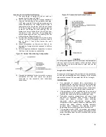
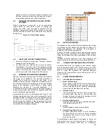
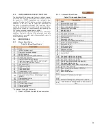
Figure 9: Sidewall Vent and Air Inlet Configuration
* Always check local codes for minimum distance above
ground or snow levels
Summary of Contents for DynaMax DMH081
Page 2: ......
Page 68: ...65 PART 14 EXPLODED VIEW PARTS LIST DYNAMAX HS WALL HUNG...
Page 69: ...66 DYNAMAX HS FLOOR MOUNT...
Page 76: ...73 PART 15 ELECTRICAL DIAGRAMS 15 1 DM 80 299 INTERNAL WIRING DIAGRAM...
Page 77: ...74 15 2 DM 399 800 INTERNAL WIRING DIAGRAM...
Page 78: ...75...

