Camus Hydronics Dynaforce Series Installation And Service Manual Download Page 13

13 


2.1.3 

APPROVED VENTING MATERIALS 

Exhaust Vent for Use  for Dynaforce® Category ll or lV 

Installations  

1  Manufactured prefabricated UL/ ULC listed vent of AL29-

4C or equivalent, Single or Double Wall. 

2  316L stainless steel is limited to use in applications where 

there is no possibility of contaminants in the air such as 

refrigerants, chlorine etc. 

3  “BH” type. 

4  PVC and CPVC Schedule 40 or 80 approved to ULC S636 

5  PVC-DWV approved to comply with ANSI/ASTM D2665 

(US Jurisdictions ONLY when permitted) 

6  PVC Schedule 40 approved to comply with ANSI/ASTM 

D1785 (US Jurisdictions ONLY when permitted) 

7  CPVC Schedule 40 approved to comply with ANSI/ASTM 

F441. (US Jurisdictions ONLY when permitted) 

8  Polypropylene approved to comply with ULC S636 up to 12” 

diameter. 

NOTE 

1)  Use of cellular core PVC (ASTM F891), cellular core 

CPVC or Radel® (polyphenosulfone) in venting systems 

is prohibited. 

2)  Covering non-metallic vent pipe and fittings with thermal 

insulation is prohibited. 


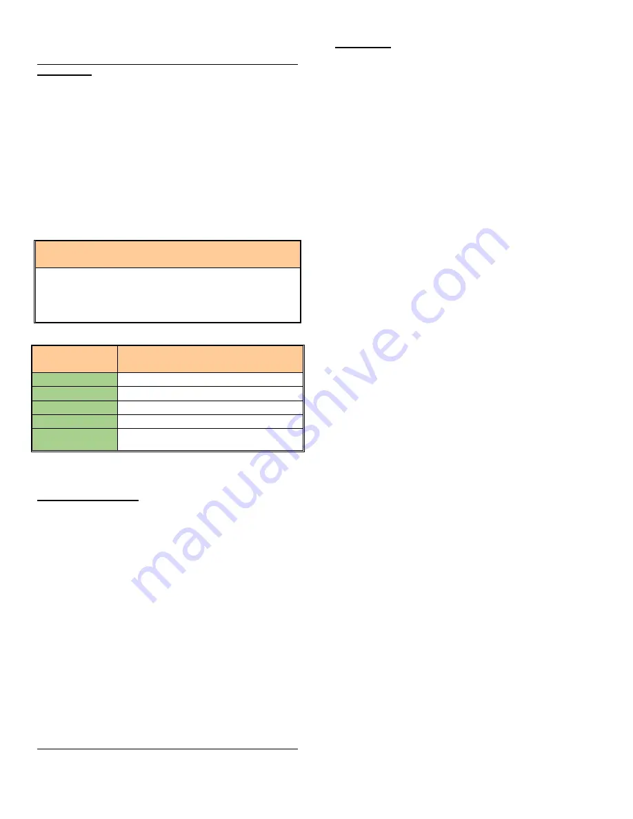
Table 4: Maximum Flue Temperature for Various Vent Materials 

Vent Material 

Maximum Flue Temperature [

o

F] 

PVC 

149 

CPVC 

194 

Polypropylene 

230 

AL29-4C 

300+, limited only by rating of seals


316L Stainless 

Steel 

300+, limited only by rating of seals


Stack temperature is 10-15

o

F above boiler inlet temperature 

when operating at steady-state. 


Vent material selection  

When selecting vent material take into consideration that 

appliances installed near a corrosive or potentially corrosive air 

supply must be isolated from it or they will suffer damage to the 

appliance and the venting system.  
The corrosion resistance of AL29-4C is typically higher than that 

of 316L. Always choose the venting system which best satisfies 

the requirements of the application

This recommendation does not supersede local codes or 

the provision of the B149 in Canada or the National Fuel 

Gas Code in the United States 

Single wall air intake pipes are to be insulated 5 feet from wall 

toward the interior of the building to minimize external sweating. 


Intake Air (Supply Air, or Fresh Air) Piping for Direct Vent 

Applications 

Air intake material must be of a type listed by a nationally 

recognized testing agency. 


PVC 

Non Foam Core Pipe.  

CPVC

 Non Foam Core Pipe.  

Polypropylene


ABS 

(Acrylonitrile-Butadiene-Styrene). 


Single wall vent pipes to be insulated 5 feet from wall toward the 

interior of the building to minimize external sweating. 

2.1.4 

VENT TERMINATION CLEARANCES 

  Do not terminate the vent in a window well, stairwell, alcove, 

courtyard or other recessed area. The vent cannot 

terminate below grade. The bottom of the vent terminal shall 

be located at least 12 inches (30cm) above grade and 

above normal snow levels. In all cases the appliance shall 

be installed in accordance with local codes. 

  The vent outlet MUST NOT terminate below a forced air 

inlet at any distance. 

  The vent cannot terminate below grade. Position the vent 

termination where vapours will not damage walls or plants 

or may otherwise be objectionable. 

  The vent terminal shall not be installed closer than 3 feet (1 

m) from an inside corner of an L-shaped structure, window 

well, stairwell, alcove, courtyard or other recessed area as 

wind eddies could affect boiler performance or cause 

recirculation. 

  DO NOT terminate closer than 4 feet (1.25m) horizontally 

and vertically from any electric meter, gas meter, regulator, 

relief valve, or other equipment. In all cases local codes 

take precedence 

  Position terminations so they are not likely to be damaged 

by foreign objects, or exposed to a build-up of debris.  

  The vent piping must terminate in an elbow pointed outward 

or away from the air inlet. 

  To avoid a blocked flue condition, keep the vent 

cap/terminal clear of snow, ice, leaves, debris, etc. 

  Flue gases from this appliance may contain large amounts 

of water vapour that will form a white plume in winter. Plume 

could obstruct a window view. 

  Flue gas condensate can freeze on exterior walls or on the 

vent cap. Frozen condensate on the vent cap can result in 

a blocked flue condition. Some discoloration to exterior 

building surfaces can be expected. Adjacent brick or 

masonry surfaces should be protected with a rust resistant 

sheet metal plate. 

2.1.5 

INLET CAP FOR ROOFTOP TERMINATION 

The air inlet cap consists of two 90° elbows installed at the point 

of termination for the air inlet pipe. The first 90° elbow is installed 

on the rooftop at the highest vertical point of the air inlet pipe 

and turned horizontal; the second 90° elbow is screened and is 

installed on the horizontal outlet of the first elbow and turned 

down. A 90° elbow and a 90° street elbow may be used to make 

this assembly. If a straight piece of pipe is used between the two 

elbows, it should not exceed 6" (150mm) in length.  

2.1.6 

LOCATION OF A ROOFTOP AIR INLET AND VENT 

CAPS 

  The point of termination for the combustion air inlet cap 

MUST be at least 3 feet (0.91M) below the point of flue gas 

termination (vent cap) if it is located within a 5 foot (1.5M) 

radius of the flue outlet. Use care to ensure that the 90° 

elbow assembly is properly installed on the air inlet pipe.  

Summary of Contents for Dynaforce Series

Page 1: ...tch do not use any phone in your building Immediately call your gas supplier from a neighbour s phone Follow the gas supplier s instructions If you cannot reach your gas supplier call the fire departm...

Page 2: ...99 0171 REV 0 9...

Page 3: ...14 2 1 10 COMBINED COMBUSTION AIR INLET 14 2 1 11 DRAIN TEE 14 2 2 CONVENTIONAL VENTING INDOOR INSTALLATIONS 15 2 2 1 AIR REQUIRED FOR COMBUSTION AND VENTILATION 15 2 2 2 EXHAUST FANS 15 2 3 OUTDOOR...

Page 4: ...ROLLER 25 5 9 ERROR TABLE 26 PART 6 CONTROL PANEL 27 6 1 APPLIANCE TEMPERATURE CONTROLLER 27 6 2 CONFIGURE MENU 44 6 3 LEAD LAG SETUP UP TO 8 BOILERS 45 6 4 LOCAL REMOTE SWITCH 46 6 5 COMM PORT 2 ACTI...

Page 5: ...ECTION FOR A HEATING BOILER SYSTEM Optional 63 PART 11 INSTALLATIONS 64 11 1 CHECKING THE INSTALLATION 64 11 2 CHECKING THE INSTALLTION 64 11 3 INSPECT RECHARGE CONDENSATE COLLECTION NEUTRALIZING RESE...

Page 6: ...y received In case there is damage or a shortage immediately notify carrier Figure 2 Checking the Dynaforce Do not attempt to pry any panel off To begin disassembly you must first remove the two machi...

Page 7: ...t temperature is satisfied 2 Power to the gas valves is turned off 3 Combustion air fan ramps to a stop over the factory preprogrammed time period of 60 seconds 4 Thermostat is now in a standby mode w...

Page 8: ...s practical close all building doors and windows and all doors between the space in which the appliances remaining connected to the common venting system are located and other spaces of the building I...

Page 9: ...60cm 12 30cm 12 30cm 24 60cm 600 24 60cm 12 30cm 12 30cm 24 60cm 800 24 60cm 12 30cm 12 30cm 24 60cm 1000 24 60cm 12 30cm 12 30cm 24 60cm 1200 24 60cm 12 30cm 12 30cm 24 60cm 1400 24 60cm 12 30cm 12...

Page 10: ...by a moving vehicle DO NOT install this appliance in any location where gasoline or flammable vapors are likely to be present DO NOT install this appliance on top of carpet flooring Appliance must be...

Page 11: ...4 70 1 2 20 3 4 59 1 2 13 56 3 8 1 7 8 23 1 4 12 6 10 8 7 8 5 2 1 2 1 1 4 845 1400 29 3 8 31 3 4 73 1 2 22 5 8 62 1 2 14 59 1 4 1 7 8 23 1 4 12 6 10 8 7 8 5 2 1 2 1 1 4 845 1600 29 3 8 31 3 4 73 1 2...

Page 12: ...system must be provided in compliance with local codes and other applicable codes All connections should be secured and sealed per the vent manufacturers specifications When a Positive vent system is...

Page 13: ...ot terminate the vent in a window well stairwell alcove courtyard or other recessed area The vent cannot terminate below grade The bottom of the vent terminal shall be located at least 12 inches 30cm...

Page 14: ...ION Follow Category II or IV vent termination and all General instructions The vent terminal should be vertical and exhaust outside the building at least 2 feet 0 61M above the highest point of the ro...

Page 15: ...unit is installed with a proper venting system 2 2 1 AIR REQUIRED FOR COMBUSTION AND VENTILATION Provisions for combustion and ventilation air are to be in accordance with the section for Air for Com...

Page 16: ...lly The vent terminal MUST NOT terminate below a forced air intake at any distance Do not terminate the vent in a window well stairwell alcove courtyard or other recessed area The vent cannot terminat...

Page 17: ...1 2 1 800 2 1 2 1 2 2 1000 2 1 2 1 2 2 1200 2 1 2 2 2 2 1400 2 2 2 2 3 2 1600 2 2 3 2 3 2 1800 2 2 3 2 3 2 2000 2 2 3 2 3 2 2500 3 2 3 2 3 1 2 3 3000 3 2 3 2 3 1 2 3 3500 3 2 3 3 4 3 4000 3 3 4 3 4 3...

Page 18: ...alve Figure 9 DR500 1800 1 1 Negative Pressure Air Gas Ratio Control Valve Figure 10 DR2000 5000 1 1 Air Gas Ratio Control Valve Figure 11 DR3500 5000 SKP25 Regulating Gas Valve Actuator SSOV 3 5 DIFF...

Page 19: ...necessary steps to provide proper gas pressure to the control If gas supply pressure is within normal range proceed to remove gas manometer and replace pressure tap fittings in the gas piping to the...

Page 20: ...require the routing of these bleeds and vents to the atmosphere outside the building Proper routing of vent lines to the atmosphere from the factory supplied termination points is the responsibility...

Page 21: ...50 water and 50 propylene glycol is the preferred method of freeze protection in hydronic systems This mixture will protect the appliance to approximately 35 F 37 C To maintain the same temperature ri...

Page 22: ...miniums apartments and motels and typically used in conjunction with tempering valves to achieve temperature control In some applications it may be appropriate to provide a flow through tank to act as...

Page 23: ...ulating pump is controlled by the Dynaforce temperature control SOLA When the appliance is activated by a remote operating signal the pump will start and run for the operating cycle and for a post pur...

Page 24: ...h the latest edition of the National Electrical Code ANSI NFPA No 70 When the unit is installed in Canada it must conform to the Canadian Electrical Code C22 1 Part 1 and or local Electrical Codes All...

Page 25: ...lize a hot surface ignition system DR3000 DR5000 models utilize a proven pilot The ignition control proves the presence of the flame using a flame rectification voltage 0 8Vdc energizes the main gas v...

Page 26: ...hooting procedure Figure 22 Lockout Condition To eliminate the lockout error 1 Press the red bar indicating a Lockout condition 2 Press the Lockouts button Figure 23 Lockout History 3 Press Clear Lock...

Page 27: ...e minimum off time per stage Display of run hours for maintenance purposes Counter wraps around at 10000 hours Flame failure signal JST and Molex connectors for ease of service Error message display i...

Page 28: ...witch Flow Switch Low water cutoff if equipped Water Pressure Switch 30 PSI Gas Pressure Switch Low gas pressure switch 4 5 w c N O High gas pressure swtich 14 w c N C Blocked flue switch N C Interrup...

Page 29: ...fixed setpoint Modulates on boiler inlet sensor default Heat demand is generated when Remote Operator is closed 1 Place toggle switch to LOCAL 2 Press and 3 Press CH Central Heat Configuration 4 Pres...

Page 30: ...mperature WWSD 6 Select Minimum outdoor temperature Outdoor Design 7 Select Low Water Temperature Min Water Temp 8 Select Outdoor boost maximum off point Design Max 9 Press CH Central Heat Configurati...

Page 31: ...J3 ECOM connector 4 Place toggle switch in LOCAL 5 Press and 6 Press Outdoor Reset Configuration 7 Select Enable Enable 8 Select Maximum outdoor temperature WWSD 9 Select Minimum outdoor temperature...

Page 32: ...er inlet sensor default Heat demand is generated when Remote Operator is closed and 4 20mA or 2 10Vdc signal is present 1 Place toggle switch in LOCAL 2 Press and 3 Press CH Central Heat Configuration...

Page 33: ...4 Press Advanced Settings 5 Press the to arrive at Central Heat 6 Select Modulation rate source S2 J8 6 4 20mA and burner on off 7 Place toggle switch to REMOTE for remote operation if required Syste...

Page 34: ...W Sensor Stat operation 1 Press Sensor Configuration 2 Select S6S7 J9 1 3 Sensor DHW 10K NTC Single Non Safety 3 The control will proceed into a Lockout 2 condition 4 Press Verify Begin Yes 5 Press th...

Page 35: ...35...

Page 36: ...n Access 4 Verify MB1 Modbus address 1 5 Verify MB2 Modbus address 1 6 Select Lead Lag Master Configuration 7 Select Master Enabled Enabled Fixed Setpoint operation 8 Enter CH Setpoint Fixed setpoint...

Page 37: ...The following steps are performed at the factory and verifying on site will be sufficient 16 Select Pump Configuration 17 Press Advanced Options 18 Press the to arrive at Central Heat Pump or DHW Pump...

Page 38: ...uential order 5 Select Lead Lag Slave Configuration 6 Select Slave Enabled Enable slave for built in Lead Lag master The following steps are performed at the factory and verifying on site will be suff...

Page 39: ...r boiler system sensor configuration 1 Press and 2 Press Sensor Configuration 3 Select S5 J8 11 Sensor 4 Connector Type 10K NTC Single Non Safety 5 The control will proceed into a Lockout 2 condition...

Page 40: ...e 10K NTC Single Non Safety 5 The control will proceed into a Lockout 2 condition 6 Press Verify Begin Yes 7 Press the reset button on the ignition control within the alotted time Master Boiler 8 Pres...

Page 41: ...41 17 Press Show Line to confirm reset curve 18 Press the to arrive at Warm Weather Shutdown 19 Select Enable Shutdown after demand ends...

Page 42: ...on time user defined Base load rate adjustment Description Electrical Connection s Programming Instructions Upon a call for heat the lead boiler will fire to the specified base load rate 80 If the tem...

Page 43: ...ot within Error threshold 5o F of setpoint after Interstage delay 2 minutes a lag boiler will be brought online and will also fire up to the base load rate specified This method will then be repeated...

Page 44: ...whenever a call for heat is present ON ON Pump is constantly powered Pump Output Pump B Specify pump contact Over run time 1 5 min Post pump time Default 1 min Use for local Stand alone demands Use f...

Page 45: ...R300 1000 3000 RPM DR1200 5000 20 0 Ignition Fan speed 6 2 6 Sensor Configuration Menu Group Selection Sub Menu Group Selection Parameter Selection Description Sensor Configurations S1 J8 4 sensor 10K...

Page 46: ...2 minutes Base Load Rate When a call for heat is initiated the lead boiler runs up to the desired base load rate Default 80 and continues to operate in this fashion based on the above 4 scenarios If...

Page 47: ...llowing are pertinent Table 13 Variable Frequency Drive Parameters Parameter Function Settings 1 High Low Voltage Input Voltage 120 220 240 460 480 01 02 2 Carrier Frequency 03 4 Stop Method 03 5 Stan...

Page 48: ...48...

Page 49: ...combustion through the heat exchanger and venting system The fan assembly consists of a sealed housing and fan wheel constructed from spark resistant material The fan is operated by a fully enclosed 1...

Page 50: ...performance at full input and at minimum input Depending on field conditions the CO2 metering valve may require some minor adjustment at full input Refer to Table 14 Adjustment at minimum input can be...

Page 51: ...ests button 3 Move the firing rate slider to maximum RPM as indicated by the test sticker 4 Press Start Test to operate the boiler at max fire for 5 minutes Locate the input adjustment screw on the to...

Page 52: ...itch power back on and allow the burner to fire Ignition should be smooth Normally the differential gas pressure will be identical to the differential air pressure Actual differential pressure may var...

Page 53: ...the burner Alert 110 291 294 To reset the module refer to section 5 8 2 Verify that all air has been purged from gas line Inspect hot surface igniter and related wiring for damage and connection erro...

Page 54: ...reads between 3 w c and 14 w c L P Gas Pressure should be at 11 w c Air Gas Mixture Issue Refer to Section 8 3 Gas Valve Adjustment Procedure for proper combustion setting Air Inlet and or Vent confi...

Page 55: ...30 PSI Temperature Overshoot Stack temperature has exceeded the limit temperature Alert 125 The stack temperature has exceeded the maximum temperature allowed PVC 149o F CPVC 194o F AL29 4C Stainless...

Page 56: ...y Check external wiring for voltage feedback Check internal wiring for proper connections Check the flame sensor and verify that it is clean Replace Dynaforce Controller if necessary Blank Display Scr...

Page 57: ...stem request occurred 50 Modulation Fault DR300 1000 ONLY 54 56 Processor brown out 61 Anti short Cycle 62 Fan speed not proved 63 LCI off safety circuit is open 68 Setpoint was overridden due to sens...

Page 58: ...etected by the flame sensor A minimum signal of 0 8Vdc must be detected by the flame sensor to prove the flame Check flame sensor wire Within harness bundle Move flame sensor wire away from harness bu...

Page 59: ...one of more of the boiler safety switches are in an open condition when it is to be in a closed condition before the ignition sequence is allowed to proceed Flow Switch Gray Check flow switch Green Op...

Page 60: ...Before this error appears the combustion air blower will slow down in an effort to prevent such an error from occurring Verify pump motor load to pump rated load Low current reading Purge air from wa...

Page 61: ...performed by a Camus trained service technician Proper service is required to maintain safe operation Properly installed and adjusted units seldom need flue cleaning All gaskets sealant on disassembl...

Page 62: ...and replace as necessary Gaskets affected by heat will not reseal properly and must be replaced Replace the burner in the reverse order that it was removed Insert the igniter and sensor before doing t...

Page 63: ...er is provided on the secondary side of the transformer A tripped circuit breaker indicates a short in the 24VAC controls and must be corrected 10 12 COMBUSTIBLE MATERIALS CAUTION Keep appliance clear...

Page 64: ...be isolated for service An air separation device must be supplied in the installation piping to eliminate trapped air in the system Locate a system air vent at the highest point in the system The sys...

Page 65: ...ve 9 Review the installed gas piping from the meter to the boiler Ensure that the gas pipe meter and any regulators are adequately sized 10 Review the field wiring and electrical service for both the...

Page 66: ...iping for multiple unit installations will require larger minimum pipe sizes and tank circulating tapping to ensure proper flow If the temperature rise is too low the water velocity is too high Adjust...

Page 67: ...67 PART 12 EXPLODED VIEW 19 1 2 3 4 5 6 7 8 9 10 11 12 13 14 15 16 17 18 20...

Page 68: ...68 21 22 23 24 26 35 34 33 32 31 30 29 28 27 25 36 37 38 39 40 42 43 56...

Page 69: ...59 61 59 1 34 27 44 Red Silicone Gasket White Graphite Ceramic Gasket White Ceramic Gasket Only required if heat exchanger surface is rough or uneven Graphite Gasket Burner Heat Exchanger 62 63 64 65...

Page 70: ...14011 X X 90 14013 X 90 15209 X X 90 15210 X 90 14017 X 90 15099 X 90 2010 X X 90 2011 X 90 2012 X 5 Base Support 14 1025 X X X X X X X X X 14 1073 X X X X X X 14 1018 X X 14 1071 X X X 7 Condensate...

Page 71: ...4 1022 X 14 1061 X 14 8085 X X X 14 1008 X 14 1028 X 14 1015 X 14 1065 X X 14 1049 X 14 1069 X 16 Top Cover 14 6030A X X X X X X X 14 5228A X X X X X X 14 5329 45 50 X X X X 14 5329 60 X 17 Back Panel...

Page 72: ...lator Body VGG10 404U X X X X 26 Low gas Switch C6097A X 27 Main Burner 66 5015 350 X X 66 5015 500 X X 66 5015 800 X X 66 5015 1000 X X 66 5015 1400 X DF 1500 BRN X X DF 1750 BRN X DF 2000 BRN X DF 3...

Page 73: ...SV222N04TXB X X X ESV402N04TXB X X 44 Transition Arm 14 5560 X X X X X X X 45 Pilot Tube 11 0015 X X X X X 46 Blocked Flue Switch SMD 8021205256 X 47 Air Proving Switch NS2 1427 00 X 48 Intake Adapter...

Page 74: ...0057 X X X X X X X 63 Air Inlet to Fan Adapter 16 0016 X 64 RG175 Fan Gasket 33 0038 X 65 DR300 400 1 8 Red Gasket 33 0058 X X X 66 Air Inlet to Fan Adapter 16 0015 X X X 67 RG148 Fan Gasket 33 0037...

Page 75: ...75 PART 13 ELECTRICAL DIAGRAMS...

Page 76: ...76...

Page 77: ...77...

Page 78: ...78...

Page 79: ...79...

Page 80: ...rvice Dynaforce 1 100 6 100 2 100 7 100 3 100 8 100 4 100 9 100 5 100 10 100 The exchanged or repaired heat exchanger will carry the balance of the remaining original warranty provided with the applia...

Page 81: ...e components supplied Such costs are the responsibility of the owner DISCLAIMERS Camus shall not be responsible for any water damage Provisions should be made that in the event of a water appliance or...

Page 82: ...ing boilers as well as a supplier of specialty HVAC products Our service line is open 24 hours 7 days a week The CAMUS CERTIFIED seal assures you that Reliability Efficiency Serviceability are built i...

Reviews: