CPS-EP2000(R2) MANUAL
Camtec Power Supplies GmbH - Gewerbestrasse 30 - DE-76327 Pfinztal / Germany
P.9/19 (01/2018.01.1)
Tel. +49 (721) 46596 - 0 Fax +49 (721) 46596 - 77
www.camtec-gmbh.com
-
(Subject to alterations. This product is not designed to be used in applications such as life support systems wherein a failure or malfunction could result in injury or death)
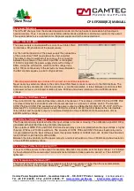
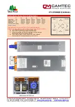
Compensation of Load Line Drop Voltage (Sense ++/--) battery charger operation mode
Remote Sensing as a battery charger
If the CPS-EP power supply unit is used as a battery charger, it is recommended to refrain from sensing. It can
lead to severe damage to the power supply, if the polarity of the sense line is confused (field experience: such
error often occurs when system service is required, e.g., when the batteries are changed). If it is necessary to
use sensing, proceed as described in the figure below. Proven approaches are 250mA for the fuses and 3...5A
load capacity of diodes.
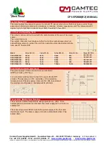
Current Distribution in Parallel Mode (CS), CSB Current Share Bus
To increase the output current, up to 5 units of the same model and output voltage can be operated in parallel.
The operator shall ensure that the output voltage of each involved unit shall be set to the same value and with a
maximum tolerance of ±0,5%. Derate the total output current by 5% to prevent the unit from overload operation.
In parallel operation, a uniform current distribution between the participating power supplies is important. To
prevent one of the power supplies going early into the current limitation and display error message. An uneven
load and thus premature aging of the participating devices is prevented. (further information on page 12)
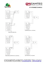
Connect CON3 contact 5 (CS) to contact 13 of the next device. Are other devices involved in the parallel
operation, you may grind the CS bus through from unit to unit. The current division between the devices will be
performed automatically. The accuracy of the current distribution is ±5% at I
out
≥
0,5x I
out
max.
Set the DIP switch S11 to the OFF position if you like to apply CS-mode operation. The factory set of the DIP
switch S11 is ON (no CS operation).
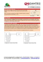
External Shutdown (SD)
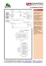
The power supply is set to the Shutdown mode, when the
control input is either shorted via a relay contact, a switch
contact or an NPN transistor with open collector (voltage drop
<1V, current typ. 1,5mA). Alternatively, a voltage of 10 to 30V
(typ. 12V/1.5mA, 24V/5.5mA) can be applied.
If the shutdown repeals the power supply starts with a delay of
35ms.
Using the softstart the current and the voltage rises within
100ms continuously to the default set values. Between control
input SD, power input, and power output is a reinforced
Isolation of max. 400Vdc and a basic isolation of max. 600Vdc
working voltage.
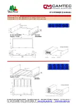
Set Voltage Range via Potentiometer (Uadj)
The power supply is equipped with 1 potentiometer Uadj for setting the voltage. The current limiting is fix.
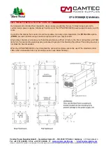
Continuous Mode Operation Device
The device provides continuous current while overloaded and the voltage goes down.


