Camtec 3041101002CA Manual Download Page 8


CPS-EP2000(R2) MANUAL


Camtec Power Supplies GmbH  -  Gewerbestrasse 30  -  DE-76327  Pfinztal / Germany   

P.8/19 (01/2018.01.1) 

Tel. +49 (721) 46596 - 0  Fax +49 (721) 46596 - 77    

www.camtec-gmbh.com

   -   

[email protected]


(Subject to alterations. This product is not designed to be used in applications such as life support systems wherein a failure or malfunction could result in injury or death) 


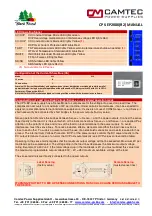
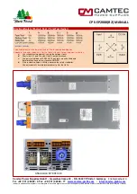
LED Operating Signal 

CV/OVP  CV Constant Voltage Mode LED lights Green 

OVP Overvoltage maloperation or interference voltage LED lights Red 

CC/OCP  CC Constant Current Mode LED lights Yellow 

(1)


OCP Over Current Protection LED lights Red 

TA/OT 

TA Temperature Alarm LED lights Yellow, warning temperature shutdown pending 

(1)


OT Over Temperature Shutdown LED lights Red 

INH/FF 

INH Inhibit (Interlock) Shutdown LED lights Yellow 
FF Fan Failure LED lights Red 

SD/SB 

SD Shutdown LED lights Yellow 
SB Standby LED lights Red 

(1)


(1) 

Not available for EP-series 


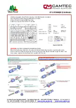
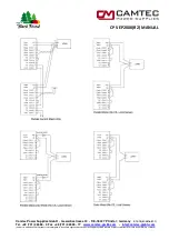
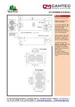
Configuration of the Current Share Bus (CS) 

Mode 

S11 

S12 

CS active 


CS non-active 


Warning!


CS (Current Share Mode) only applies when a current distribution must take place while parallel 

operation mode. In single or parallel operation without the need of CS, always switch CS with S11 to OFF=1. 
Factory set: CS non-active (S11=1) 
Note that for DIGI3201 interface equipped unit settings will be made with the browser in the software. 


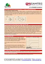
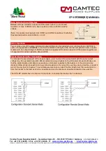
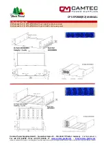
Compensation of Load Line Drop Voltage (Sense ++/--), standard operation mode 

The CPS-EP power supply has a Sense Mode to compensate for the voltage drop over long load lines. The 
compensation amounts to a maximum of 2V per load line. Under certain circumstances, it can be expected to 
apply more complicated external interference suppression. If sense is not used, CON4 Sense +/+ and Sense -/- 
shall necessarily be connected by short bridges to the power outputs (factory setup). 
 
Sense operation: Remove the bridges between Sense +/+, Sense -/- and the power outputs. Connect the sense 
lines directly to the load. It is irrelevant which of the local connections Sense +/+ and Sense -/- are applied. Pay 
attention to the polarity of plus and minus of the load to prevent damage to the power supply. To avoid 
interference, twist the sense lines. To reduce inductive effects, we recommend that the load lines position is 
close to each other. To supply a pulsating load, the use of an electrolytic capacitor and a cermic capacitor has 
proved. The internal Over Voltage Protection (OVP) of the power supply controls the DC power directly to the 
DC output terminals. In case of an error the OVP acts automatically (see OVP values corresponding table).  
 
Operating in the sense mode requires that the maximum output voltage will not be exceeded. Maximum 2V per 
load lead can be compensated. The voltage drop in the load lines decreases the maximum output voltage 
rating. Example of a 30V unit: if the total voltage drop in the load leads is 2V you must subtract this value from 
the maximum programmable output voltage 30V – 2V = 28V maximum available voltage at the load. 
 
The sense terminals are directly connected to the power outputs. 


Lokal Sensing


Remote Sensing


                               (factory setup)                                                                                    (twisted sense lines) 


WARNING! PROTECT TO MIX UP SENSE CONNECTIONS. THIS COULD CAUSE SERIOUS DAMAGE TO 
THE DEVICE.


Summary of Contents for 3041101002CA

Page 1: ...l positions PFC 0 99 Features 3D Heat Dissipation CSB Current Share Bus Inhibit for safe interlocking Remote Shutdown Sense mode Current Monitoring 0 5V Power Good Relay DC ok Precise dynamics on load change Series parallel operation up to 100kW EMC conducted class B radiated class A Efficiency 92 94 PFC Powerfactor 0 99 Variable controlled fans from Papst Long lifetime under hard operation Solid ...

Page 2: ...ons call for the highest standards of safety and interference suppression The device was developed in accordance with the requirements of EN61010 1 EN61010 2 201 EN62368 1 and the EMC standards EN55032 conducted Class B radiated Class A The mechanical design of the CPS EP2000 device series is unique It is the first power supply line in the world market which can be flexibly adapted to any installa...

Page 3: ...switching contacts Inhibit Mode Interlock The inhibit circuit reliably prevents unintentional starting of the power supply The control loop is internally locked Since this blocking is done progressively it is active even when the control signal is missing due to a cable break or temporarily suspend A premature restart of the power supply is prevented The inhibit input can be connected to a relay o...

Page 4: ...al shutdown autorecovery 70 C outside measuring point distance 10mm Hold Up Time 30ms 230Vac mains buffering at full load Inrush Current 14 6Aeff 20 7Apeak 230Vac active electronic inrush protection no simple NTC Startup Delay typ 1s Softstart typ 100ms Ambient Temperature 20 C 60 C operating derating 2 5 C 50 C Storage Temperature 40 C 85 C Ambient Conditions Humidity 95 non condensing 25 C clima...

Page 5: ...onnected No Function 3 DGND Digital Ground 4 NC NC Not Connected No Function 5 NC NC Not Connected No Function 6 NC NC Not Connected No Function 7 FF Output Signal Fan Failure Open Collector 8 NC NC Not Connected No Function 9 OT Output Signal Over Temperature Open Collector 10 NC NC Not Connected No Function 11 NC NC Not Connected No Function 12 NC NC Not Connected No Function 13 NC NC Not Connec...

Page 6: ...8 01 1 Tel 49 721 46596 0 Fax 49 721 46596 77 www camtec gmbh com info camtec gmbh com Subject to alterations This product is not designed to be used in applications such as life support systems wherein a failure or malfunction could result in injury or death Schematic of the internal circuits CON1 4 NC NC ...

Page 7: ...wercon powercon 20 a nac3fca CON1 Push In 0 14 1 5mm AWG26 16 CON2 CON3 CON4 DC M8 200A 60 C 250Vac 20A Neutrik PowerCon 3x2 5 mm Neutrik NAC3FCA Interface pluggable Push Pull Connectors from Weidmueller included Input Power Connector Neutrik NAC3FCA included Output Power Connection M8 Powerbars Lock Pins snap into the 2U 3U 19 subrack WARNING OUTPUT CONNECTION INSTRUCTION Mount the cable lugs dir...

Page 8: ...drop over long load lines The compensation amounts to a maximum of 2V per load line Under certain circumstances it can be expected to apply more complicated external interference suppression If sense is not used CON4 Sense and Sense shall necessarily be connected by short bridges to the power outputs factory setup Sense operation Remove the bridges between Sense Sense and the power outputs Connect...

Page 9: ... the participating power supplies is important To prevent one of the power supplies going early into the current limitation and display error message An uneven load and thus premature aging of the participating devices is prevented further information on page 12 Connect CON3 contact 5 CS to contact 13 of the next device Are other devices involved in the parallel operation you may grind the CS bus ...

Page 10: ...forced Isolation of max 400Vdc and a basic isolation of max 600Vdc working voltage DC OK Relay DC Power Good The signal DC OK has potential free relay contacts changeover The contacts of CON1 Pin2 and CON1 Pin4 are closed relay coil is energized when the power operates as a connstant voltage source The contacts CON1 Pin2 and CON1 Pin4 are open when the power output is inhibited by SD INH OT FF OVP...

Page 11: ...lues to protect the unit from operating under overload conditions also see OT thermal SD Model Value UA1 V Value IA1 A Value UA2 V Value IA2 A Pmax IA1 IA2 CPS EP2000 024 30Vdc 66 7A 24Vdc 84A 2001 2016W CPS EP2000 036 45Vdc 44 4A 36Vdc 56A 1998 2016W CPS EP2000 048 58Vdc 34 5A 48Vdc 42A 2001 2016W CPS EP2000 072 90Vdc 22 2A 72Vdc 28A 1998 2016W CPS EP2000 110 150Vdc 13 3A 110Vdc 18 2A 1995 2002W ...

Page 12: ...plicable to EN62368 1 Due to the dielectric strength of the internal components used only the models with an output voltage of 48Vdc and later are approved for series operation Other power supplies are not approved for series operation above 60Vdc Parallel Operation N 1 Decoupling To increase the overall power of the power supply up to 5 units of the same model with the same output voltage may be ...

Page 13: ...l Germany P 13 19 01 2018 01 1 Tel 49 721 46596 0 Fax 49 721 46596 77 www camtec gmbh com info camtec gmbh com Subject to alterations This product is not designed to be used in applications such as life support systems wherein a failure or malfunction could result in injury or death ...

Page 14: ...cal Safety Factory Test Field Test Owner 48Vdc 2800Vdc Type and factory test are the manufacturer While repating damage can happen to the power supply unit For the field test owner follow the below instruction a Use suitable test equipment raising the voltage slowly b Short circuit L1 and N and all the DC output terminals c Use only test voltages of 50 60Hz The outputs are unearthed and therefore ...

Page 15: ...result in injury or death Mechanics Aluminium housing IP20 Cooling is achieved via front to rear fans To ensure adequate heat dissipation 50mm to the front and 150mm blockade free distance from the device back wall must be guaranteed The harnesses are to be designed and installed to that the air outlet of the unit is not being blocked In a rack mounting of multiple subracks the rear distance of th...

Page 16: ...ww camtec gmbh com info camtec gmbh com Subject to alterations This product is not designed to be used in applications such as life support systems wherein a failure or malfunction could result in injury or death 19 Subrack 2U 3U 2U Subrack for 1 3 CPS EP2000 with up to 6kW continuous power 3U Subrack for 1 5 CPS EP2000 with up to 10kW continuous power ...

Page 17: ...to custom design power supplies Steplessly hard mount of the CPS EP2000 3000 power supply modules in a 3D room In practice that means that one can mount the modules into every angle imaginable Our 3D Heat Dissipation 3D HD ensures optimal cooling in each mounting position you may consider All you may consider is to make sure that at least a distance of 5cm 2 Inch to the front cooling slots and 15c...

Page 18: ...ion Article Number CPS EP2000 024 R2 24Vdc model incl analogue interface 3041101002CA CPS EP2000 036 R2 36Vdc model incl analogue interface 3041101003CA CPS EP2000 048 R2 48Vdc model incl analogue interface 3041101004CA CPS EP2000 072 R2 72Vdc model incl analogue interface 3041101005CA CPS EP2000 110 R2 110Vdc model incl analogue interface 3041101006CA Certifcate Calibration Separate works certifi...

Page 19: ...bolts or operation outside the specified herein specification or in an unsuitable environment has the immediate loss of warranty to follow We disclaim any responsibility for any resulting damage to persons or things 4 Note The device must not be operated without an upstream circuit breaker CB We recommend the use of B Type 16A It is prohibited to use the unit without PE It may be necessary upstrea...

Reviews: