background image

Montage

Assembly bands designed to be mounted on a mast should be inserted into the corresponding holes
in the rear of the body of the device and firmly tighten. Attach the device to the mast with the an-
tenna pointed directly at the point of receiving. Be sure to use two bands. Bands contained in the
kits are designed for outdoor installation and resistant to UV radiation, which guarantees safety.

WARNING

The antenna of the transmitter must "see" optically with an antenna of receiving part.  
Do   not   install   the   devices   at   distances   of   less   than   0.5   m   from   each   other.  
It is recommended to use a minimum distance of 1 m.

Install receiver and antenna directed exactly to the transmitting point.

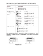
Set the desired operating channel according to the table. Channel numbers and polarity of antennas
should be the same in both cooperating transceivers.
Connect the power cables with power.
The device must be powered from the supplied AC adapter 48V PoE which is also used to power IP
camera with a power consumption up to 15.4W.

WARNING


MASTER receiver and all SLAVE transmitters must be set to the same operating channel
to each connection established. Each next set working nearby must be set to a different
operating channel.

For advanced (not required):


MASTER receiver and all SLAVE transmitters must be set to

the same operating channel to each  connection  established. Each next set working nearby
must be set to a different operating channel.

For   advanced   (not   required):   VueNet   EasyLink   enables   logging   in   to   the   Web   panel   and
checking   multiple   link   parameters,   eg.   the   strength   of   the   radio   signal.  To   log   in   to   your
dashboard, connect the VueNet EasyLink to a computer with network card set compatible
with addresses according to the table on page 3. Start the web browser and enter the IP ad-
dress of the wireless device (see table p. 3).

Login Information:

User: camsat 
password: camsat  

Note: 

The device manufacturer is not responsible for the devices that are not properly 

,protected and for related damage of the equipment and other network infrastructure.

Summary of Contents for VueNet EasyLink

Page 1: ...VueNet EasyLink ver 1 2 User s manual External wireless video and audio transmission system for IP cameras HD and UHD in the band 5 1 5 8 GHz ...

Page 2: ...e user s own modifications of the device will prevent its legal use and render the warranty null and void The device has passed through the mandatory compliance assessment and it meets basic requirements in the European New Approach Directives The product is CE marked Note This device can operate within the frequency and power ranges which might be contradictory to laws applicable in selected coun...

Page 3: ...asing which will prevent its proper use Wait until the condensed water evaporates Distances and interferences The transmission distance may vary depending on the frequency environment ra dio waves buildings weather conditions etc When the transmitter is near such equipment as the TV set R LAN wireless ne twork another transmitter or when it is placed between other radio devices then the video stre...

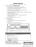
Page 4: ...al antenna MIMO 5 Ghz 2 x 14 dBi LoS range 2 5 km IP65 external housing Operating temperature from 20 C to 55 C Contents of the package VueNet EasyLink x 1 PoE power supply 48V 0 5A with European cable 230V x1 pcs Clamps x 2pcs User manual and CE Declaration of Conformity Description of connectors and LEDs RESET A button for resetting the radio module to the default settings PORT 1 PORT 2 LAN port...

Page 5: ...e with the configuration of many different cameras MASTER receiver and all SLAVE transmitters must be set to the same operating channel to establish a connection Each next set working nearby must be set to a different operat ing channel ...

Page 6: ... transmitter according to the following formula After 90 seconds since power start equipment will make a transparent interconnection sending all IP addresses connected to the ports of the device In the case of connection problems check direction of antennas and if there are no obstacles between them Change the channel number to another one Check the power supply capacity or replace to another ...

Page 7: ...lied AC adapter 48V PoE which is also used to power IP camera with a power consumption up to 15 4W WARNING MASTER receiver and all SLAVE transmitters must be set to the same operating channel to each connection established Each next set working nearby must be set to a different operating channel For advanced not required MASTER receiver and all SLAVE transmitters must be set to the same operating ...

Page 8: ...t DIPswitch No 1 to OFF transmitter mode set the channel according to the table set the transmitter number if there are more transmitters than one Connect the IP camera using the RJ45 cable to the PORT 2 Connect the supplied 48VPoE power adapter to PORT 1 Connect the second camera with a network cable RJ45 to the LAN port of the trans mitter power supply Note IP cameras will not be powered from th...

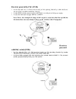
Page 9: ...oE to PORT 2 Note Due to the existing PoE voltage of 48V in port 2 connection other than specified in the instructions can cause damage to the recorder switch or other IT equipment Receiver powered with PoE switch NVR Set the dipswitch No 1 to ON receiver mode set the operating channel by a table identical to the transmitter set DIP7 and DIP8 to ON up Connect NVR equipped with PoE switch by the ne...

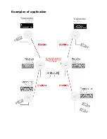
Page 10: ...Examples of application Transmitter 1 2 3 4 5 6 7 8 1 2 3 4 5 6 7 8 1 2 3 4 5 6 7 8 192 168 120 2 Channel 165 1 2 3 4 5 6 7 8 Transmitter 1 2 3 4 5 6 7 8 192 168 116 2 Channel 149 1 2 3 4 5 6 7 8 ...

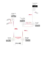
Page 11: ...Transmitter 192 168 118 5 Channel 157 1 2 3 4 5 6 7 8 1 2 3 4 5 6 7 8 1 2 3 4 5 6 7 8 1 2 3 4 5 6 7 8 1 2 3 4 5 6 7 8 1 2 3 4 5 6 7 8 ...

Page 12: ...ding to their purpose CE Europe FCC US Using other frequencies depends on the legal regu lations of the country where you are If you are not sure about regulations in your country consult your supplier WARNING The device can operate at frequencies and power which can be paid or completely prohibited in your area or your country ...

Page 13: ... due to reasons inherent to the sold device 5 Warranty repairs will be carried out in the shortest possible amount of time not exceeding 14 days counting from the moment of accepting the device for servicing If parts need to be imported the repair deadline may be extended After the repairs have been car ried out the warranty period will be extended by the repair time 7 The warrantor may refuse to ...

Page 14: ......

Page 15: ...specialised collection point Detailed information about the closest collection point is available from local authorities The proper disposal of this device allows for preserving precious resources and avoiding the negative impact on health and environment which may be endangered if the waste is handled improperly Improper waste disposal is sub ject to penalties provided for in the appropriate regu...

Reviews: