


6.
Operation
6.1
Program the Modem
It is recommended that the modem be provisioned and tested in the office
(assuming cellular coverage) rather than in the field.
6.2
Connectors and Indicators
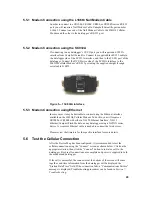
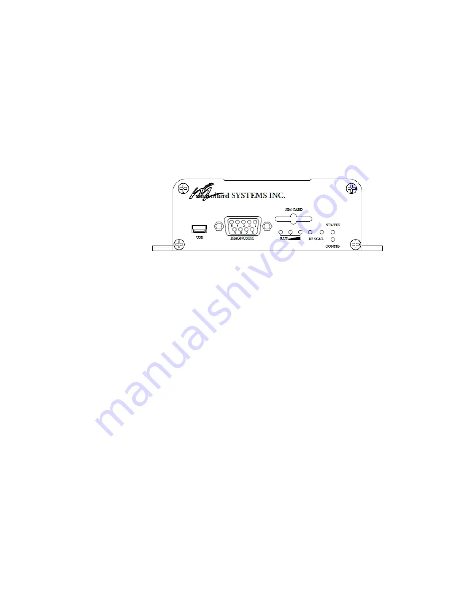
6.2.1 Modem Front
The front of the IPn3Gb Cellular Modem includes the USB port, Diagnostic
port, SIM card slot, Indicator LEDs, and Config button.
Figure 6—1 Front view of the IPn3Gb Cellular Modem
x
The USB port can be used to configure the modem. See Section
6.3.3.1 for details.
x
Currently, the Diagnostic port is not used
x
The SIM Card Slot houses the SIM card required for proper operation.
The SIM card supplied by the Service Provider must be inserted into
the SIM card slot.
x
RF LED (Red) - When connected to a 2G/EDGE or 3G-WCDMA
Network, the RF LED indicates a transmission burst. When connected
to a 3G/HSPA Network the LED has no function.
x
SGNL LED (Green) - When illuminated, the SGNL LED indicates
that the modem is connected and synchronized with a wireless carrier.
x
Receive Signal Strength Indicator (RSSI) (3x Green) - As the received
signal strength increases, starting with the furthest left, the number of
active RSSI LEDs increases. If the measured signal strength is less
than –110dBm no LED’s will be illuminated. If the signal is greater
than –105dBm, 1 LED will be on, - 100dBm equals 2 LED’s, and any
signal greater than –95dBm will show all 3 RSSI LED’s to be ON.
x
STATUS LED (Red) - Upon initial application of power the STATUS
LED will be illuminated for approximately 20 seconds, after which, it
will being to blink slowly (loading) for an additional 25 seconds, then
22