background image

Campbell Scientific Companies

Campbell Scientific, Inc. (CSI)

815 West 1800 North

Logan, Utah  84321

UNITED STATES

www.campbellsci.com

[email protected]

Campbell Scientific Africa Pty. Ltd. (CSAf)

PO Box 2450

Somerset West 7129

SOUTH AFRICA

www.csafrica.co.za

[email protected]

Campbell Scientific Australia Pty. Ltd. (CSA)

PO Box 444

Thuringowa Central

QLD 4812 AUSTRALIA

www.campbellsci.com.au

[email protected]

Campbell Scientific do Brazil Ltda. (CSB)

Rua Luisa Crapsi Orsi, 15 Butantã

CEP: 005543-000 São Paulo SP BRAZIL

www.campbellsci.com.br

[email protected]

Campbell Scientific Canada Corp. (CSC)

11564 - 149th Street NW

Edmonton, Alberta T5M 1W7

CANADA

www.campbellsci.ca

[email protected]

Campbell Scientific Ltd. (CSL)

Campbell Park

80 Hathern Road

Shepshed, Loughborough LE12 9GX

UNITED KINGDOM

www.campbellsci.co.uk

[email protected]

Campbell Scientific Ltd. (France)

Miniparc du Verger - Bat. H

1, rue de Terre Neuve - Les Ulis

91967 COURTABOEUF CEDEX

FRANCE

www.campbellsci.fr

[email protected]

Campbell Scientific Spain, S. L.

Psg. Font 14, local 8

08013 Barcelona

SPAIN

www.campbellsci.es

[email protected]

Please visit www.campbellsci.com to obtain contact information for your local US or International representative.

Summary of Contents for DCP100

Page 1: ...INSTRUCTION MANUAL DCP100 Data Collection Platform 2 99 C o p y r i g h t c 1 9 9 9 C a m p b e l l S c i e n t i f i c I n c ...

Page 2: ...ll other warranties expressed or implied including warranties of merchantability or fitness for a particular purpose CAMPBELL SCIENTIFIC INC is not liable for special indirect incidental or consequential damages Products may not be returned without prior authorization The following contact information is for US and International customers residing in countries served by Campbell Scientific Inc dir...

Page 3: ...together make sure you have the latest operating system Contact a Campbell Scientific Applications Engineer if you have any questions 2 The datalogger clock must be set to Coordinated Universal Time All references to time are based on Coordinated Universal Time 3 If you are using the keypad CR10KD when the datalogger initiates a P120 or P123 instruction the instruction will fail without reporting ...

Page 4: ......

Page 5: ... 2 4 1 Computer Base Station 2 4 2 Field Station 2 5 POWER SUPPLIES 4 5 1 12 and 24 AHr Sealed Rechargeable Batteries 4 5 2 AC Power and Deep Cycle Rechargeable Batteries 4 5 3 Datalogger s Batteries 4 6 INSTALLATION 4 6 1 Wiring 4 6 2 Battery 4 6 3 Antenna 4 7 FORWARD AND REFLECTED POWER 7 8 PROGRAMMING THE TRANSMITTER 8 8 1 Star Pound Mode 8 8 2 Establishing and Editing Parameters 8 8 3 Status I...

Page 6: ...st Transmission F 1 F 5 Toggling User Flag 2 High F 1 F 6 CR10X Data Dump Program F 1 F 7 21X Data Dump Program F 2 G LOCAL MAGNETIC DECLINATION G 1 G 1 Determining True North G 1 G 2 Prompts from GEOMAG G 1 H CHANGING THE CR10 S RAM OR PROM CHIPS H 1 H 1 Disassembling the CR10 H 1 H 2 Installing New RAM Chips in CR10s with 16K RAM H 1 H 3 Installing New PROM H 1 I 21X PROM REPLACEMENT PROCEDURE I...

Page 7: ...ews I 1 I 2 Separating the Faceplate from the Base I 1 I 3 Removing the Back Cover of the Faceplate I 2 I 4 Inside the Faceplate I 2 I 5 Removing the PROM with a Screwdriver I 2 I 6 Inserting the New PROM I 3 TABLES 6 1 1 Wiring Diagram 5 8 2 1 Parameter s Descriptions 8 8 2 2 Decimal Equivalent 9 8 3 1 60 Commands 9 9 1 1 CR10X CR10 CR510 and CR500 s Instruction Parameters 10 9 1 2 CR10X Example ...

Page 8: ...TABLE OF CONTENTS IV This is a blank page ...

Page 9: ...g each satellite to remain above a specific region This allows a user to point the GOES antenna at a fixed position in the sky There are two satellites GOES East and GOES West GOES East is located at 75 West longitude and GOES West is located 135 West longitude Both satellites are located over the equator Within the United States odd numbered channels are assigned to GOES East Only even numbered c...

Page 10: ...EQUIRED EQUIPMENT 4 1 COMPUTER BASE STATION The equipment required at the computer base station is listed below Phone modem with MNP level 4 error correction Most commercially available Hayes compatible modems contain this error checking protocol Check the operator s manual for your modem Computer with user supplied commu nication software e g Procomm Plus Crosstalk 4 2 FIELD STATION The field sta...

Page 11: ...ANTS GATES UNITED DESICCANTS GATES DO NOT EAT UNITED DESICCANTS G ATES UNITED DESICCAN TS GATES FIGURE 4 1 A Field Station Monitoring a Well s Depth Solar Panel Not Shown CAMPBELL SCIENTIFIC INC CR10 MADE IN USA WIRING PANEL NO EARTH DIFF SE AG H L AG H L AG H L AG G G E3 AG 4 5 6 7 8 9 10 11 12 G G G G 12V 12V SWITCHED 12V G 12V POWER IN SERIAL I O SE DIFF AG H L AG H L AG H L AG G G E1 E2 1 2 3 ...

Page 12: ...rge One option is to have the datalogger s batteries power the datalogger and sensors while the transmitter uses a 12 AHr battery a 24 AHr battery or a deep cycle battery NOTE The datalogger s batteries should be removed when not in use Rechargeable batteries should be trickle charged with either Solar or AC power through a charging regulator 6 INSTALLATION 6 1 WIRING The DCP100 hardware excluding...

Page 13: ...nects to TGT1 BNC female port Red Cable Connects to CH12R 12 and datalogger 12 V Black Cable Connects to CH12R and datalogger G Ground Green Cable Connects to datalogger G Ground and is routed through the enclosures ground lug and connected to earth ground Battery Connects to CH12R INT white connector Solar Panel Black and white leads connect to the two CH12R CHG Ports Polarity does not matter GOE...

Page 14: ...DCP100 DATA COLLECTION PLATFORM 6 FIGURE 6 3 2 Antenna Mounting Hardware Assembled View 1 FIGURE 6 3 3 Antenna Mounting Hardware Assembled View 2 Fits onto the 1 5 OD pipe Fits onto the 1 5 OD pipe ...

Page 15: ... when the percentage of power reflected is less than 5 A reflected power reading of 27 is 5 of 165 and 2 7 of 215 This percentage can be estimated with the following equation see the datalogger program in Appendix D 3 power reflected ref 17 4 fwd 17 4 2 x 100 1 When the percentage of power reflected is greater or equal to 5 one or more of the following situations exist and must be corrected The an...

Page 16: ...ach parameter and to advance to the next one Individual parameters can also be edited by typing in and the parameter number Remember the TGT 1 clock is not changed until the A key is pressed after the 3 rd parameter No other changes are saved until the A key is pressed after the 26 th parameter TABLE 8 2 1 Parameter s Descriptions Parameter Description 1 3 Set the transmitter s clock All scheduled...

Page 17: ...e self timed buffer a 2 to select only the random and a 3 to select both buffers These buffers must match Instruction 120 s parameters see Section 9 TABLE 8 2 2 Decimal Equivalent Number Decimal or letter equivalent 1 1 2 2 3 3 4 4 5 5 6 6 7 7 8 8 9 9 A 10 B 11 C 12 D 13 E 14 F 15 8 3 STATUS INFORMATION AND TEST TRANSMISSIONS The 60 mode is for displaying status infor mation and performing test tr...

Page 18: ...ock If the clocks differ more than 3 seconds the datalogger s clock is set to the transmitter s However only the seconds are compared Therefore the datalogger s clock is NOT reset when the minutes or hours differ The complete time HH MM SS will be updated if the clocks differ by more than 3 seconds Table 9 1 1 lists and describes Instruction 120 s parameters TABLE 9 1 1 CR10X CR10 CR510 and CR500 ...

Page 19: ...Table 1 Program 01 10 0 Execution Interval seconds Measure reference temperature 01 Internal Temperature P17 1 1 Loc RefTemp Measure thermocouple temperature 02 Thermocouple Temp DIFF P14 1 1 Reps 2 1 2 5 mV Slow Range 3 5 DIFF Channel 4 1 Type T Copper Constantan 5 1 Ref Temp Loc RefTemp 6 2 Loc TCDeg_C 7 1 Mult 8 0 Offset Measure battery voltage every 10 seconds 03 Batt Voltage P10 1 3 Loc Batte...

Page 20: ...Star Pound Mode P123 will transfer all the information needed to properly transmit data via the TGT 1 satellite transmitter The information is assigned by NESDIS See table 9 2 1 for a complete description of each parameter of P123 P123 is only available on CR10X dataloggers with version 1 6 operating system or later CR500 dataloggers with version 1 4 or later and all CR23X and CR510 dataloggers NO...

Page 21: ...ort preamble 0 98 seconds type 0 23 Selects the buffer or buffers used Type 1 to select only the self timed buffer a 2 to select only the random and a 3 to select both buffers These buffers must match Instruction P120 parameters see Section 9 Program example using P123 instruction This is not the only way to run P123 The programming theory used in this example is as follows Using a P91 statement d...

Page 22: ...d reflected power as part of the data stream 21X Instruction 70 z 0 The forward and reflected power readings are NOT placed into input locations 03 ID Where ID 0 The array ID for the data that is transferred to the TGT1 s buffer 9 3 2 Datalogger Programming Theory Campbell Scientific dataloggers are programmed via a keyboard display or an IBM PC compatible computer running PC208 software Please se...

Page 23: ...0 1 2 Reps 2 1 Loc RefTemp Transfer data to TGT1 every hour 09 If time is P92 1 0 Minutes into a 2 60 Minute Interval 3 30 Then Do Transfer data array ID 111 to the TGT1 s self timed buffer and places the transmitter s latest forward and reflected power readings into Input Locations 4 and 5 10 Data Transfer to GOES P99 1 00 Buffer Selection 2 4 FWD Ref Power Loc FwdPwr 3 111 Array ID ID 0 Transfer...

Page 24: ...urly data initiated by the P99 in instruction 10 18 If time is P92 1 5 Minutes into a 2 1440 Minute Interval 3 30 Then Do 19 Data Transfer to GOES P99 1 00 Buffer Selection 2 4 FWD Ref Power Loc FwdPwr 3 222 Array ID ID 0 Transferred to TGT1 S Buffer 20 End P95 ...

Page 25: ...a question form to complete and submit for approval Mr Marlin Perkins NOAA NESDIS E PS Room 3320 4700 Silver Hill Road Stop 9909 Washington D C 20233 9909 Phone 301 457 5681 FAX 301 457 5620 Beacon Registration 888 212 7283 Email mperkins nesdis noaa gov 2 Following approval NESDIS sends a Memorandum of Agreement MOA The MOA must be signed and returned to NESDIS 3 After the MOA is approved NESDIS ...

Page 26: ......

Page 27: ...T J 110 FOR I 1 TO J 120 DV I MID A 3 I 2 3 130 NEXT I 140 B RIGHT A LEN A 3 J 160 A B A 170 K INT LEN A 3 180 L J 190 FOR I J 1 TO L 200 DV I MID A 3 I J 2 3 210 NEXT I 270 FOR I 1 TO L 280 A ASC LEFT DV I 1 AND 15 290 B ASC MID DV I 2 1 AND 63 300 C ASC RIGHT DV I 1 AND 63 310 IF A 64 B 1008 THEN DV B 48 64 C 9000 GOTO 400 320 IF A AND 8 THEN SF 1 ELSE SF 1 330 IF A AND 4 THEN SF SF 01 340 IF A ...

Page 28: ......

Page 29: ...R ATN X1 SQR X1 X1 1 B BR 1 01745329 115 GOSUB 300 120 A1 90 C R1 A1 01745329 130 S1 6378 AH 0003048 SIN R1 140 S2 35785 6378 S1 150 A2 180 A1 R2 A2 01745329 155 S4 SQR S1 2 6378 AH 0003048 2 160 S3 SQR S4 2 S2 2 2 S4 S2 COS R2 170 X2 SIN R2 S3 S2 180 ER ATN X2 SQR X2 X2 1 E ER 1 01745329 190 PRINT ANTENNA ELEVATION ANGLE E DEGREES 200 PRINT ANTENNA AZIMUTH ANGLE B DEGREES 210 PRINT PRINT PRINT HI...

Page 30: ......

Page 31: ...3 80 0 89 17 9 1 D 2 CALCULATING POWER OUT The amount of power going out of the transmitter at the BNC connector is approximated by the following equation Approx Pout 10 log fwd 17 4 x 0 0100077 2 x 1000 50 20 8 This equation assumes the dBm is 50 ohms and the impedance match between the trans mitter and the cable antenna assembly is good power reflected less than 5 Table D 2 1 lists Pout for vari...

Page 32: ...2 11 Z Loc Scratch2 14 Z X F P37 1 11 X Loc Scratch2 2 4 3429 F 3 11 Z Loc Scratch2 15 Z X F P34 1 11 X Loc Scratch2 2 20 8 F 3 6 Z Loc Fwd_dBm 16 Else P94 17 Z F P30 1 0 F 2 0 Exponent of 10 3 6 Z Loc Fwd_dBm 18 End P95 Set the Output Flag High 10 every hour 19 If time is P92 1 0 Minutes Seconds into a 2 60 Interval same units as above 3 10 Set Output Flag High Timestamp hourly data 20 Real Time ...

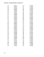
Page 33: ... 20 401 7295 69 401 8030 21 401 7310 70 401 8045 22 401 7325 71 401 8060 23 401 7340 72 401 8075 24 401 7355 73 401 8090 25 401 7370 74 401 8105 26 401 7385 75 401 8120 27 401 7400 76 401 8135 28 401 7415 77 401 8150 29 401 7430 78 401 8165 30 401 7445 79 401 8180 31 401 7460 80 401 8195 32 401 7475 81 401 8210 33 401 7490 82 401 8225 34 401 7505 83 401 8240 35 401 7520 84 401 8255 36 401 7535 85 ...

Page 34: ...1 8795 170 401 9545 121 401 8810 171 401 9560 122 401 8825 172 401 9575 123 401 8840 173 401 9590 124 401 8855 174 401 9605 125 401 8870 175 401 9620 126 401 8885 176 401 9635 127 401 8900 177 401 9650 128 401 8915 178 401 9665 129 401 8930 179 401 9680 130 401 8945 180 401 9695 131 401 8960 181 401 9710 132 401 8975 182 401 9725 133 401 8990 183 401 9740 134 401 9005 184 401 9755 135 401 9020 185...

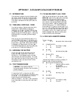
Page 35: ...ust be connected before the test or the transmitter will be damaged To cause the TGT1 to transmit use 60 command 8 The transmission will last less than 5 seconds To verify transmission occurred check forward and reflected power 60 command 3 The TGT 1 will not perform a test transmission more often than once each minute F 5 TOGGLING USER FLAG 2 HIGH After the test transmission the random buffer MUS...

Page 36: ...1 random buffer overwrite the old data 2 1 FWD Ref Power Loc Data 09 Do P86 1 22 Set Flag 2 Low 10 End P95 F 7 21X DATA DUMP PROGRAM The 21X s program is the same as the CR10X and CR10 s except Instruction 99 has an extra parameter With this parameter you specify the array of data that is transferred to the buffer see Section 9 2 ...

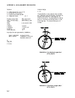
Page 37: ... determined by GEOMAG for a site near Logan Utah Declination angles east of True North are considered negative and are subtracted from 0 degrees to get True North as shown in Figure G 2 Declination angles west of True North are considered positive and are added to 0 degrees to get True North as shown in Figure G 3 Subtract declination from 360 Add declination to 0 22 E 18 E 16 E 14 E 12 E 10 E 8 E...

Page 38: ... Example of report generated by GEOMAG Model USCON90 Latitude 42 2 N Date 7 27 93 Longitude 111 51 2 W Elevation 4454 0 ft D deg min 15 59 6 Annual change 0 6 1 The declination in the example above is listed as 15 degrees and 59 6 minutes Expressed in degrees this would be 15 99 degrees As shown in Figure G 1 the declination for Utah is east so True North for this site is 360 15 99 or 344 degrees ...

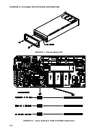
Page 39: ...et make certain that all the pins are correctly seated After installing the 32K chips check for pins that may be bent or not firmly seated in the socket If you notice a bent pin remove the chip carefully straighten it and repeat the installation procedure H 2 1 CHANGING JUMPERS There are six jumpers used to configure hardware for different RAM sizes Figure H 2 shows the jumper settings for differe...

Page 40: ...APPENDIX H CHANGING THE CR10 S RAM OR PROM CHIPS H 2 FIGURE H 1 Disassembling CR10 FIGURE H 2 Jumper Settings for Different RAM Configurations ...

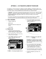
Page 41: ...tion 3 Use a Phillips screwdriver to remove the screws on both sides of the 21X L faceplate Figure I 1 1 2 3 A 4 5 6 B 7 8 9 C 0 D I D DATA 21X MICROLOGGER H L 1 H L 2 H L 3 H L 4 H L 5 H L 6 H L 7 H L 8 1 2 3 4 1 2 1 2 4 5 12 3 6 1 2 3 4 EXCITATION CAO CONTROL PULSE INPUTS SERIAL I O MADE IN USA S N 10800 6145 6146 6147 FIGURE I 1 Removing Faceplate Screws 4 Remove the faceplate from the base by ...

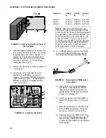
Page 42: ... 919 CD4504BEX RCA H 910 CD4504BEX RCA H 910 CD74HC138EX RCA H 849 CD74HC573EX RCA H 840 C 1994 ItemNo 6146 ObjsNo 01 C 1994 ItemNo 6145 ObjsNo 00 C 1994 ItemNo 6147 ObjsNo 02 FIGURE I 4 Inside the Faceplate Firmware Socket Socket Socket A B C OSX 0 1 6145 03 6146 05 6147 06 OSX 1 1 6145 03 6146 05 6160 05 OSX 2 1 6145 03 6146 05 6161 06 NOTE Older 21X L Microloggers pre 1986 were shipped with onl...

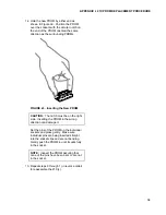
Page 43: ...New PROM CAUTION The notch must be on the right side Inserting the PROM in the wrong direction can damage it Set the pins of the PROM on the individual sockets and press gently Make sure individual pins are being inserted straight into the socket clips and are not bending Gently push the PROM in until it seats fully in the socket NOTE Inspect the PROM assuring that none of the pins have been bent ...

Page 44: ......

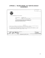
Page 45: ...J 1 APPENDIX J TELONICS MODEL TGT1 CERTIFICATION BY NOAA NESDIS ...

Page 46: ......

Page 47: ...This is a blank page ...

Page 48: ... campbellsci com br suporte campbellsci com br Campbell Scientific Canada Corp CSC 11564 149th Street NW Edmonton Alberta T5M 1W7 CANADA www campbellsci ca dataloggers campbellsci ca Campbell Scientific Ltd CSL Campbell Park 80 Hathern Road Shepshed Loughborough LE12 9GX UNITED KINGDOM www campbellsci co uk sales campbellsci co uk Campbell Scientific Ltd France Miniparc du Verger Bat H 1 rue de Te...

Reviews: