


CCFC Field Camera
8
There are two methods for a user to configure the CCFC camera: using the web
interface via Wi-Fi or Ethernet connection and using the RS-232 serial lines.
Using the web interface is the best way to set up the camera. Communicate
with the camera via the Ethernet connection or Wi-Fi in order to facilitate
focusing and targeting the camera when installed.
Setting up the camera using the RS-232 (or RS-485) serial lines on the Power
I/O cable and using Campbell Scientific’s Device Configuration software to
change configuration parameters in the camera is an alternate to using the web
interface.
Device Configuration Utility
is a free download from the Campbell
Scientific (Canada) website
www.campbellsci.ca/downloads
. The use of RS-
232 serial lines requires the use of the DB9 terminal block adapter (included in
the box with the CCFC) in order to connect to a PC (Section 7.1
Power & I/O
Cable Connections
).
7. Camera
Hardware
Ensure that the pigtail end of the power cable is properly terminated (see
Section 8
Cables
/
Wiring
) before connecting the power cable connector to the
camera. If the power supply has an on/off switch, it is recommended to switch
the power off before connecting the power connector to the camera.
When power is first applied to the camera, the LED on the
Setup Button
will
turn on and remain steadily on for about 90 seconds. Once the LED starts
flashing, the camera has properly initialized and is ready for operation (see
Section 7.2
Setup Button/Status LED
).
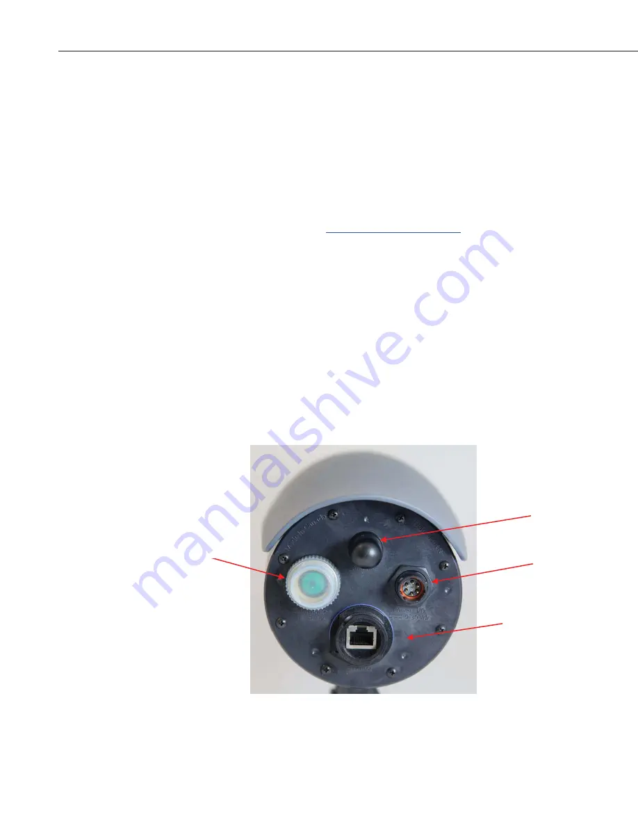
Figure 7-1 CCFC Connector Layout
Ethernet
Power I/O
(9-30 Vdc)
Setup Button
LED Status
Antenna


