Campbell CCFC Field Camera Instruction Manual Download Page 81

CCFC Field Camera 


67 

12.8.2.3.2


  Existing Network 

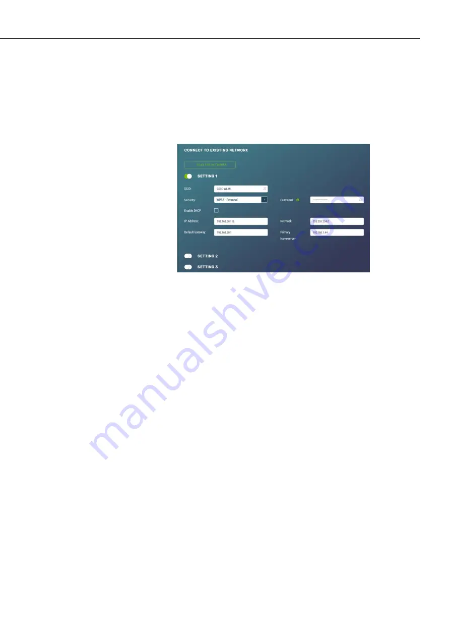
The Wi-Fi settings information appears when the camera Wi-Fi is 
configured to operate with an existing network. Typically, this 
mode would be used when the camera is regularly connected to 
an existing Wi-Fi network to transfer files or to eliminate the 
need to connect a wired Ethernet cable. 


Figure 12-31 

Connect to Existing Network


The 

Scan


For


Networks

 button appears when the 

Access Mode

 is 

in 

Existing Network

. This button searches for nearby Wi-Fi access 

points and displays a list. The list includes the name, address, 
channel, signal strength, network, and encryption types. There are 
also buttons which copy the selected AP information into the 
configuration section for ease of use, which appear when the 

Connected to Existing Network 

option is selected. 

After performing a scan for Wi-Fi networks, the user can quickly 
copy the selected network information into one of three client 
settings by pressing the button in the result table. After this step, 
if the Wi-Fi network is using encryption, the password must be 
entered into the password box in order to connect.  

Typically, this is all that is required to connect to a Wi-Fi 
network, as nearly all networks supply configuration information 
using DHCP. However, if necessary, the process can be done 
manually. 

When the camera tries to connect to a Wi-Fi network, it will 
perform a scan and connect to the first network that is configured 
in the list. For example, if networks in both settings 1 and 2 are 
present, the camera will use settings 1. 

There are also eight settings associated with each Wi-Fi client 
connection as shown in Table 12-19 

Existing Network Settings for 

Wi-Fi Clients

Summary of Contents for CCFC Field Camera

Page 1: ...INSTRUCTION MANUAL CCFC Field Camera May 2016 Copyright 2016 Campbell Scientific Canada Corp...

Page 2: ......

Page 3: ...under guarantee or not Please state the faults as clearly as possible and if the product is out of the guarantee period it should be accompanied by a purchase order Quotations for repairs can be give...

Page 4: ......

Page 5: ...ore beginning work Wear a hardhat and eye protection and take other appropriate safety precautions while working on or around tripods and towers Do not climb tripods or towers at any time and prohibit...

Page 6: ......

Page 7: ...nsity nonvisible IR 850 nm LEDs for night vision illumination Do not make physical contact with the IR LEDs or place any body part near the IR LEDs less than 5cm while the camera is powered on When in...

Page 8: ......

Page 9: ...up Button Status LED 11 7 2 1 Status LED 11 7 2 2 Setup Button 12 7 3 Camera Memory 13 7 3 1 Link to Most Recent Photo and Video 13 7 3 2 FTP Photo Collection from Camera Memory 14 7 4 Modem Power Con...

Page 10: ...6 2Video Capture 55 12 7 File Explorer 58 12 8 Settings 59 12 8 1General 59 12 8 1 1SNTP 61 12 8 2Network 62 12 8 2 1Wired Ethernet Settings 63 12 8 2 2Wi Fi Settings 64 12 8 2 3Wi Fi Access Mode 65...

Page 11: ...ER 95 15 3 4Example Program Adding GPS Coordinates to the Photo Banner DATALOGGER 96 15 4 PakBus Neighbouring Address 97 16 Power Calculations and Timings 97 16 1 Standalone Operation 97 16 2 Operatio...

Page 12: ...2 12 Motion Detect 43 Figure 12 13 Motion Detect Create New Profile 45 Figure 12 14 Lens Position 49 Figure 12 15 Lens Position Modal 49 Figure 12 16 Lens Position Modal in Capture Modes 49 Figure 12...

Page 13: ...107 Figure 20 3 CCFC Mounted to Crossarm 108 Tables TABLE 4 1 Power Mode Summary 7 TABLE 6 1 CCFC Factory Default Configuration 9 TABLE 7 1 Setup Button Status LED 12 TABLE 8 1 Power I O Cable Connect...

Page 14: ...2 24 Camera Power Modes 75 TABLE 12 25 Capture Response Time 77 TABLE 12 26 Ethernet Power Modes 78 TABLE 12 27 Wi Fi Power Modes 79 TABLE 12 28 Import Export Settings 85 TABLE 12 29 Users 89 TABLE 13...

Page 15: ...ptions include Ethernet Wi Fi RS 232 and RS 485 The CCFC is fully web enabled with HTTP FTP and Email capabilities Campbell Scientific s PakBus protocol is supported by the CCFC for integration with C...

Page 16: ...C Full functionality of the motorized zoom lens is available in the temperature range of 30 C to 60 C Image and video capture can still occur but the motorized lens will remain in a fixed position at...

Page 17: ...ignal Logic Low Level 0 65 V 20 Vdc Absolute Min Logic High Level 2 0 Vdc 20 Vdc Absolute Max Communication Interfaces Ethernet 10 100 RS 232 port or RS 485 port Wi Fi supports 802 11bgn in the 2 4 GH...

Page 18: ...claims with the shipping company Immediately check package contents against the shipping documentation Contact Campbell Scientific about any discrepancies The model number and cable length are printed...

Page 19: ...10 seconds or by using the Power Icon on the web interface Always ensure that all cable connectors and covers are securely in place Record any changes to the IP settings of the camera This information...

Page 20: ...rface see Section 12 4 2 External Trigger c Motion Detect Enable and configure Motion Detect Capture To set this up using the web interface see Section 12 4 3 Motion Detect 2 Select the Power Mode tha...

Page 21: ...y On Always On 90 mA 10 20 Full Power Save Mode 10 mA 10 20 Deep Sleep Always On 6 mA 15 25 Full Power Save Mode 6 mA 15 25 Off State Always On 1 mA 90 120 Full Power Save Mode 1 mA 90 120 This table...

Page 22: ...ements Although the CCFC is designed to be a rugged and reliable device for field use care should be taken when handling or moving it to avoid aesthetic damage Other than the desiccant there are no us...

Page 23: ...O Port RS 232 or RS 485 RS 232 Baud Rate 115200 PakBus Address 55 There are two methods for a user to configure the CCFC camera using the web interface via Wi Fi or Ethernet connection and using the R...

Page 24: ...ra If the power supply has an on off switch it is recommended to switch the power off before connecting the power connector to the camera When power is first applied to the camera the Status LED on th...

Page 25: ...e up 7 2 Setup Button Status LED The Setup Button is located behind a protective cap on the camera The Setup Button also contains an integrated Status LED for user feedback 7 2 1 Status LED The Status...

Page 26: ...uously On The camera is booting up this process takes approximately 90 sec The camera will be required to boot up whenever Power is first applied to it The camera is exiting the Off Power mode to perf...

Page 27: ...Title will be used to organize the photos in the directory This is set up Media Settings see Section 12 6 Media Settings The use of camera memory for media storage is entirely configurable to suit the...

Page 28: ...esired to collect a large number of files from an entire folder using the web interface is cumbersome It is recommended to access the CCFC memory using the FTP file transfer process On most Windows ma...

Page 29: ...ly reduce the system power requirements by only turning on the modem when required to transmit a photo or video The Modem Power Control will turn on under the following conditions The camera is in one...

Page 30: ...the last position that was in focus to perform the capture The auto focus operation attempts to focus on the most distant object in the field of view For example in a scene with mountains in the backg...

Page 31: ...The wiring for the Power I O Cable connector assembly and which wires need to be connected for the intended camera application is as shown in Table 8 1 Power I O Cable Connections The wires can be ter...

Page 32: ...S 232 and RS 485 communications are used for PakBus or the Device Configuration Utility Connect to an unused terminal block Yellow Modem Power Control Output This line is intended to power a communica...

Page 33: ...jacket IP 68 rated connector at the camera end 10 inch pigtail for termination at the datalogger end 3 Single Pole 16 20AWG Grey Push Operated Connector Terminals Maximum recommended cable length is 2...

Page 34: ...en the CCFC and a local network router cellular modem or laptop Details of the Environmental Ethernet Cable are CAT5E Shielded cable with polyurethane jacket IP68 environmentally rated RJ45 connector...

Page 35: ...Utility Connect the camera to the serial port of a PC using the DB9 FEMALE to Terminal Block Adaptor as shown in Section 13 RS 232 Communications Once the camera is powered up this can typically take...

Page 36: ...as a bright sky or a dark horizon the photo may contain portions that are under exposed and portions that are over exposed as with most cameras The CCFC utilizes various techniques to produce the bes...

Page 37: ...directs the user to the camera s web interface where the camera can be configured 11 2 Setup Using Ethernet 11 2 1 Link Local IP Address Auto Configuration The CCFC supports an automatic IP address co...

Page 38: ...odecs are available on the computer The download is available online at http www videolan org vlc Download and install the appropriate VLC media player to the PC that will be interfacing with the CCFC...

Page 39: ...t rtsp 192 168 1 78 ipcam mpeg4 pluginspage http www videolan org type application x vlc plugin In the embed code 192 168 1 78 needs to be changed to the IP address of CCFC being used 12 1 2 UPnP Disc...

Page 40: ...Field Camera 26 View live video Retrieve photo and video files from the camera memory Access all camera settings Create zoom set points Figure 12 1 Dashboard Desktop view Figure 12 2 Dashboard Mobile...

Page 41: ...re is an opportunity to select a Lens Preset from a drop down and to adjust the Zoom using a slider Edit Positions directs users to the Lens Position option See Section 12 5 Lens Positions for detaile...

Page 42: ...f the camera is the Dashboard There are no operational settings to change on the Dashboard However a manual photo capture can be initiated from this page If any settings are changed or added the Save...

Page 43: ...ion they would like to view from use the Edit button to go to Lens Position see Section 12 5 Lens Position or adjust the zoom level of the live stream video Using the Capture Now button allows a user...

Page 44: ...seconds see Section 7 2 Setup Button Status LED 12 2 3 Set Up Progress Bar The Set Up Progress bar is visible on every web page When proceeding through the Set Up Progress workflow to configure the C...

Page 45: ...be viewed in the Manual Capture modal see Figure 12 7 Manual Capture Modal The quality of the capture is Lossless Download Navigates to the File Explorer to download captured photos Time and Date 24 h...

Page 46: ...recording the live video until the number of seconds has elapsed Video pre recording allows the camera to record up to 30 seconds of video leading up to a related capture event This feature can only b...

Page 47: ...hen Timed Capture is enabled the CCFC uses its internal clock as a trigger to initiate the capture of photos or video In addition to the primary Timed Capture event there is also a second independent...

Page 48: ...CCFC Field Camera 34 Figure 12 9 Timed Capture Create New Profile...

Page 49: ...5 Lens Position Selecting the green position title opens the Lens Position modal to edit the selected lens position Enable Photo Capture Toggle Initiates the capture of photos and opens the photo cap...

Page 50: ...ion 12 8 3 2 Email Media Profile Drop down to select a configured media profile Use the Edit button to setup Media profiles via the Media Settings modal see Section 12 6 Media Settings Send via FTP To...

Page 51: ...Lens Position Selecting the green position title opens the Lens Position modal to edit the selected lens position Enable Video Capture Toggle Enables video capture and opens the video capture settings...

Page 52: ...FTP Destination Drop down to select a configured FTP profile Use the Edit button to setup FTP profiles via the FTP Settings modal see Section 12 8 3 1 FTP Send via PakBus Toggle Enabling initiates se...

Page 53: ...period is 10 milliseconds msec Preferably pulses should be short in duration milliseconds No less than 1 sec between captures is recommended with no more than 5 in a 10 second period The voltage leve...

Page 54: ...positive voltage Active Low Configures the External Trigger to capture with 0 volts Lens Position Checkbox Select 1 4 lens positions for the capture See Section 12 5 Lens Position Selecting the green...

Page 55: ...o select a configured media profile Use the Edit button to setup Media profiles via the Media Settings modal see Section 12 6 Media Settings Send via Email Toggle Enable to initiate sending photos via...

Page 56: ...Video Duration Sets length of video capture event Maximum is 60 seconds Pre Record Duration Sets length of video to be recorded before capture event Maximum is 30 seconds Camera must be set to Fully...

Page 57: ...te sending videos via FTP Destination Drop down to select a configured FTP profile Use the Edit button to setup FTP profiles via the FTP Settings modal see Section 12 8 3 1 FTP Send via PakBus Toggle...

Page 58: ...is the only user configurable parameter for Motion Detect operation A value of 1 provides the least sensitive motion detect threshold setting and a value of 99 provides the most sensitive motion detec...

Page 59: ...cond 10 seconds for a 5MP photo Figure 12 13 Motion Detect Create New Profile TABLE 12 8 Motion Detect Settings for Photo Options Variable Allowable Values Description Enable Opens Motion Detect Creat...

Page 60: ...reached Continuous Overwrite management will start deleting the oldest files once the camera memory is full or the allocated memory size max space setting from above is reached Sub Folder Date Format...

Page 61: ...ings modal see Section 12 6 Media Settings TABLE 12 9 Motion Detect Settings for Video Options Variable Allowable Values Description Enable Opens Motion Detect Create New Profile to add parameters Tit...

Page 62: ...space setting from above is reached Sub Folder Options An option is given to store photos in a sub folder named by YY MM or YY MM DD Selecting the YY MM DD option has some performance advantages when...

Page 63: ...ited to suit a user s requirements These positions are saved to the camera memory to optimize media capture events If no lens position is set for the event the camera will continue to use the current...

Page 64: ...s in and out close up to wide angle Manual Focus Slider Slider automatically updates when the Zoom slider is moved as the camera automatically focuses on the center of the screen The Manual Focus slid...

Page 65: ...entimetres 0 10 100 10 200 10 300 10 400 10 500 10 600 10 700 75 800 500 900 300 1000 80 12 6 Media Settings The camera comes with four default Media Settings which can be edited Media Settings dictat...

Page 66: ...ettings are significant in determining how the camera will operate The description of the parameters for the Photo Capture setup are outlined in Table 12 11 Photo Capture Variables Figure 12 18 Media...

Page 67: ...Text Title Drop down None Date and Time Numerical Increment from 1 Enter the number to start the increment from Enable File Capture Toggle When viewing the photo this information will be displayed Pos...

Page 68: ...nal temperature of the camera TABLE 12 13 Photo Resolution Details Resolution Size with Outside Banner Maximum Characters in Banner Quality Typical File Size kB 320 x 176 320 x 192 45 Lossless 32 Very...

Page 69: ...g the Video Capture the Media Setting Edit Video Profile web page appears There are two subtabs that provide two independent types of video to be recorded The video resolution and frame rate are the t...

Page 70: ...CCFC Field Camera 56 Figure 12 20 Media Settings Edit Video Profile Figure 12 21 Video Settings Modal...

Page 71: ...verwritten in the camera memory every time a video is recorded Date and Time each file will have a timestamp appended to it Ex Video1_2011_01_28_14_22_10 avi Numerical Increment a unique number is app...

Page 72: ...ubfolders as well as individual photos or videos Be cautious when using the Delete Selected function Each capture event is allocated a set amount of space on the camera memory based on the inputted Ca...

Page 73: ...e Capture Mode see Section 12 4 Capture Modes Clicking on one of the main folders displays the contents inside Another set of subfolders will be displayed within the main folder The camera creates sub...

Page 74: ...ith Local Time when selected the local time and date are displayed for verification Set Manually input date and time values in drop down menus provided Synch with SNTP Server a means of synchronizing...

Page 75: ...ecting Sync with SNTP Server from the drop down opens the SNTP Server Address box where the server automatically receives time updates which can be configured See http www pool ntp org en for a list o...

Page 76: ...cess to the web interface the browser must be restarted with the new configuration For example if the IP address of the camera is changed the changes will be accepted by clicking on the Save button Th...

Page 77: ...ables DHCP operation of the network interface Operates as a Static IP address if Disabled unchecked IP Address 1 2 3 4 Only set if DHCP is Disabled Gain IP address from a network administrator Netmask...

Page 78: ...le to access the wired network The Wi Fi on the camera can connect to an existing network or become a Wi Fi access point By default the camera Wi Fi will be set up as an access point with a name such...

Page 79: ...are revealed allowing the user to customize the way the AP works Typically AP mode would be used in an installation where the camera was not sending files out via the Wi Fi interface to an external n...

Page 80: ...be used DHCP Start Number e g 10 0 010 Start of the address range to give to connecting clients DHCP End Number e g 10 0 0 19 End of the address range to give to connecting clients AP Security None WE...

Page 81: ...appear when the Connected to Existing Network option is selected After performing a scan for Wi Fi networks the user can quickly copy the selected network information into one of three client settings...

Page 82: ...The network mask to use when connecting to the Wi Fi network Default Gateway The network gateway to use for Internet traffic Primary Name Saver The DNS server to use for address resolution 12 8 3 File...

Page 83: ...be enabled in the Capture Modes see Section 12 4 Capture Modes When specifying an FTP connection the user can select between active and passive mode file transfers The default setting is passive mode...

Page 84: ...In active mode the client establishes the command channel but the server establishes the data channel Passive In passive mode the client establishes both channels In that case the server tells the cl...

Page 85: ...ction 12 4 Capture Modes SMTP Address Text Enter the SMTP server address that is being used Enter the SMTP server port number as part of the SMTP address if required The camera will default to Port 25...

Page 86: ...associated with the email account When troubleshooting email connectivity use the Show Password checkbox to ensure the password entered is correct 12 8 3 3 PakBus PakBus is used to enable media files...

Page 87: ...logger which allows for remote retrieval using the datalogger s communication device Both RS 232 and RS 485 are available The preferred setting is determined at the time of ordering Contact Campbell S...

Page 88: ...address of the device the camera will communicate with or send files to PakBus Neighbour 0 to 4095 Physically enter the address of the PakBus device to connect to the CCFC PakBus communication lines...

Page 89: ...ng communications Moderate Power Save Mode Not recommended Full Power Save Camera is always on Average power consumption is reduced by 50mA 12 Vdc The Ethernet is normally turned off and is only enabl...

Page 90: ...n 6mA typically is not affected by the Ethernet Power Mode Ethernet RS 232 or RS 485 communications are non responsive in Deep Sleep mode Moderate Power Save Mode Not recommended Full Power Save Mode...

Page 91: ...Ethernet Power Mode Ethernet Power Mode dictates the Ethernet power draw To reduce power consumption the CCFC includes the ability to control the power characteristics of the Ethernet port The specif...

Page 92: ...is in Partially On power mode If the camera is in the Partially On power mode then incoming data packets will wake up the camera for communications Full Power Save Mode This power mode should be used...

Page 93: ...On the other hand if the camera needs to operate from a battery for long periods of time then the Off State is more suitable There are two methods to wake the Wi Fi up when it is configured for a low...

Page 94: ...ght that is nearly invisible to the human eye Do not look directly at the front of the camera when the LEDs are on as they can cause severe eye damage The infrared IR LEDs on the camera are used to ta...

Page 95: ...when the camera is in night mode giving the camera extra sensitivity in dark scenes without having to use the IR LEDs When the IR LEDs are enabled and switched on the IR filter automatically switches...

Page 96: ...Some modems require a warm up time or a period of time to register on a network The Early Power On option is there for this purpose Enter a value in seconds the maximum value that can be entered is 3...

Page 97: ...Figure 12 44 Lens Defroster Control Always On If Prior to Capture is selected the camera will wake up prior to any of the Timed Capture schedules and turn on the heater if the temperature is below the...

Page 98: ...Degrees Minutes Seconds or Decimal Degrees When Degrees Minutes Seconds is selected Latitude North or South and Longitude East and West must be selected from the drop down and numerical values for de...

Page 99: ...re also compatible with the Device Configuration Utility Figure 12 49 Import Export Camera Settings TABLE 12 28 Import Export Settings Variable Options Description Upload Configuration File Choose fil...

Page 100: ...le Download Button Downloads the configuration file to the connected device Downloading the configuration file is useful when setting up multiple cameras with the same function The option to download...

Page 101: ...file send as is to camera Once the firmware update process is completed the Dashboard will be displayed indicating that the process is complete The camera will reboot itself It will take a few minute...

Page 102: ...fault cameras are shipped with the security authentication disabled When Authentication is set to Enable users will be prompted for a User Name and Password before access is given Ensure that a record...

Page 103: ...og into the interface Confirm Password Text Must be identical to the password If a user needs to be removed from the User List this must be done by a user with Admin access Remember that any deletion...

Page 104: ...Scientific provides and to send photo files from the camera to other devices using the PakBus protocol This value is displayed on the web interface under Settings File Transfer PakBus Figure 13 1 PakB...

Page 105: ...RS 232 Port Wire Colour Function Connection Required Red Power 9 to 30 Vdc Black Shield Pin 5 and Power Ground White Rx input Pin 3 Green Tx output Pin 2 The required RS 232 connections to a datalogge...

Page 106: ...rface of the Device Configuration Utility Confirm that the PakBus port parameter of the Communications Setting is reading RS 485 Set the RS 485 BAUD rate to match the BAUD rate of the device being con...

Page 107: ...ng distance telephone connections can be avoided by scheduling photo transfers from the camera to the datalogger outside the scheduled data collection time If a station is called on the hour to retrie...

Page 108: ...to 255 characters including null terminator The camera variable names are CCFCStillBanner1 CCFCStillBanner2 CCFCVideoBanner1 CCFCVideoBanner2 The variable for controlling the window defroster is nume...

Page 109: ...l begin the countdown again from 65 Sending a zero value using this variable will not turn off the defroster regardless of which method was used to turn it on The defroster commands should be sent to...

Page 110: ...tt_volt Enter other measurement instructions tempstring FormatFloat PTemp 2 2f BannerString Panel Temp tempstring If TimeIntoInterval 0 5 Min Then SendVariables SendVarResult Com1 0 55 0000 400 Public...

Page 111: ...entering the address of the PakBus device connected to the CCFC PakBus communication lines allows the neighbour to relay communication between the CCFC and the final destination for data Leave PakBus...

Page 112: ...nds TABLE 16 1 Power Consumption Standalone Operation Power Mode Ethernet Power Save Mode Quiescent Current Draw Max 12Vdc Active Current Draw Max 12Vdc Active Duration Amp Hr Per Day 2 JPG Day Amp Hr...

Page 113: ...uenced by two main factors the size of the photo or video and the transfer speed used to send the file The amount of time the camera is on will be increased as the size of the file becomes larger or a...

Page 114: ...e in Quiescent Low Powered State Quiescent minutes 1440 minutes per day Active minutes Quiescent minutes 1440 22 1418 minutes Determine the power consumed by the Quiescent state in Amp Hours Quiescent...

Page 115: ...Communications The pigtail end of the CCFC Power I O cable can be terminated directly to the datalogger wiring panel control ports COM1 4 Refer to Section 8 Cables Wiring for wiring details The CCFC...

Page 116: ...he CCFC will not send any files using the PakBus that are greater than 2 MB 18 2 Datalogger Files Manager The Files Manager setting on the datalogger facilitates the management of jpeg and avi files t...

Page 117: ...g or avi In Figure 18 1 this value is JPG Count dictates the maximum number of files stored with this file name If the datalogger processes more files than specified the datalogger will delete the old...

Page 118: ...r configuration Once configured File Retrieval is used to retrieve photos and video from a datalogger Figure 19 1 File Retrieval Setup Screen Select the required Retrieval Mode for the application The...

Page 119: ...t Directory is C Campbellsci LoggerNet If required the preferred location can be found by browsing The Max Files parameter specifies the maximum number of files that can be retrieved during each sched...

Page 120: ...D compact flash module The devices show up in the left hand side of the File Control panel To view files of a certain device simply click on the desired device listed in the panel Figure 19 3 USR Driv...

Page 121: ...FC Mounting Kit The camera is equipped with a set of three 20 threaded mounting holes see Figure 20 2 These mounting holes are centred along the bottom of the camera and are spaced 1 0 25 4 mm apart f...

Page 122: ...intended target Figure 20 3 CCFC Mounted to Cross arm 21 Maintenance The CCFC requires little maintenance Keeping the camera lens window clean is important for the longevity of the camera and photo an...

Page 123: ...longer capture times than other photo resolutions When a 5 MP photo is captured the continuous video stream is paused the photo sensor is reconfigured and then the 5MP photo is captured This longer de...

Page 124: ......

Page 125: ...cation device or trigger the CCFC to initiate photo or video capture Ordering part number 1 CCFCCBL1 L L is length in feet Details 20 AWG 1 pair twisted 24 AWG 2 pair individually shielded cable with...

Page 126: ...AT5E Cable with polyurethane Jacket RJ45 Environmental Connector on one end and rugged Metal RJ45 connector on the other end Maximum length 70 m 230 ft RoHS Compliant Figure A 2 CCFCCBL2 L Environment...

Page 127: ...CCFC Field Camera A 3 A 4 L28840 DB9 FEMALE To Terminal Block Adaptor Details DB9 FEMALE to terminal block interface with hood and hardware kit Figure A 4 L28840 DB9 FEMALE To Terminal Block Adapt...

Reviews: