


2
use. Always reconnect the air line
BEFORE loading any fasteners. The
nailer could eject a fastener causing
death or serious personal injury.
G
Protect your eyes and ears. Wear
Z87 safety glasses,
with side shields.
Wear hearing
protection. Employers
and users are
responsible for
ensuring the user or anyone near
the nailer wears this safety
protection. Serious eye injury or
permanent hearing loss could
result.
G
Do not use a
check valve or
any other fitting
which allows air
to remain in the
nailer. Death or
serious personal injury could occur.
G
Never place
hands or any
other body parts
in the nail
discharge area
of the nailer.
The nailer might
eject a fastener and could result in
death or serious personal injury.
G
Never carry the
nailer by the air
hose or pull the
hose to move the
nailer or a
compressor. Keep
hoses away from
heat, oil and sharp edges. Replace
any hose that is damaged, weak or
worn. Personal injury or tool
damage could occur.
G
Always assume the nailer contains
nails. Never use the nailer as a toy.
Do not engage in horseplay. Always
keep others at a safe distance from
the work area in case of accidental
discharge of nails. Never point the
nailer at anyone. Accidental
triggering of the nailer could result
in death or serious personal injury.
G
Do not drive a
nail on top of
other nails. The
nail could glance
and cause death
or a serious
puncture wound.
G
Do not operate
or allow anyone
else to operate
the nailer if any
warnings or
warning labels
are not legible.
Warnings or warning labels are located
on the nailer magazine and body.
G
Never leave the nailer unattended or
connected to an air compressor when
not in use. Serious personal injury
can occur if someone picks up and
uses the nailer without knowing the
correct way to operate the nailer.
G
Do not drop or throw the tool.
Dropping or throwing the tool can
result in damage that will make the
tool unusable or unsafe. If the tool
has been dropped or thrown,
examine the tool closely for bent,
cracked or broken parts and air
leaks. STOP and repair before using
or serious injury could occur.
Caution indicates a
potentially
hazardous situation which, if not
avoided, MAY result in minor or
moderate injury.
G
Do not modify or alter the nailer or
any nailer parts. Do not use the nailer
if any shields or guards are removed
or altered. Do not use the nailer as a
!
CAUTION
hammer. Personal injury or tool
dam.occur.
G
Avoid long extended periods of work
with the nailer. Stop using the nailer
if you feel pain in hands or arms.
G
Always check
that the
Work Contact
Element
(WCE) is
operating
properly. A
nail could
accidentally
be driven if
the WCE is not working properly.
Personal injury may occur (See
"Checking the Work Contact
Element" Section).
G
Disconnect air supply and release
tension from the pusher before
attempting to clear jams because
fasteners can be ejected from the
front of the nailer. Personal injury
may occur.
Notice indicates
important
information, that if not followed, may
cause damage to equipment.
G
Avoid using the nailer when the
magazine is empty. Accelerated
wear on the nailer may occur.
G
Clean and check all air supply hoses
and fittings before connecting the
nailer to an air supply. Replace any
damaged or worn hoses or fittings.
Tool performance or durability may
be reduced.
G
Air compressors providing air to the
nailer should follow the
requirements established by the
American National Standards
Institute Standard B19.3-1991;
Safety Standard for Compressors for
Process Industries. Contact your air
NOTICE
Model IFN3490 and IFN2190
Operating Instructions
!
WARNING
IFN2190
IFN3490
• REQUIRES
(SCFM with 16
nails per minute @ 90 psi)
4.1
4.1
• AIR INLET
1/4” NPT
1/4” NPT
• NAIL LENGTH RANGE
2” to 3
1
⁄
2
”
2” to 3
1
⁄
2
”
• NAIL SHANK RANGE
0.113” to 0.131”
0.113” to 0.131”
• MAGAZINE CAPACITY
60-75
75-105
• WEIGHT
8 lbs. 5 oz.
8 lbs. 11 oz.
• LENGTH
19.5”
19.75”
• HEIGHT
15”
15”
• MAXIMUM PRESSURE
120 psi
120 psi
• PRESSURE RANGE
70 - 120 psi
70 - 120 psi
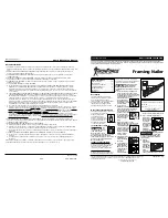
Nailer Components And Specifications
7-Sp
Manual de Instrucciones
Modelo IFN3490 and IFN2190
Adjustable Direction
Exhaust Deflector
Threaded Hole/Tool
Balancer (M8 x 1.25)
Nail Loading Area
Magazine
Single Cycle
Trigger
Warning Labels
Nail Discharge
Area
Work
Contact
Element
Hay una fuga de aire en el
área de la válvula del gatillo
Hay una fuga de aire entre la
cubierta y la boquilla
Hay una fuga de aire entre la
cubierta y la tapa
La clavadora deja de clavar un
clavo
La clavadora funciona
lentamente o pierde su
potencia
Hay clavos atascados en la
clavadora
Hay una fuga de aire en el
vástago de la válvula del gatillo
Los anillos en O de la cubierta de la válvula del
gatillo están dañados
Los tornillos de la cubierta están flojos
Los anillos en O están dañados
La defensa está dañada
Los tornillos están flojos
El empaque está dañado
La defensa está desgastada
La boquilla está sucia
La suciedad o daños evitan el desplazamiento
libre de los clavos o el mecanismo de impulso en
el cargador
El resorte del mecanismo de impulso está dañado
El flujo de aire hacia la clavadora es inadecuado
El anillo en O del pistón está desgastado o le
falta lubricación
Los anillos en O de la válvula del gatillo están
dañados
Hay fugas de aire
Hay una fuga en el empaque de la tapa
La clavadora no está bien lubricada
El resorte de la tapa del cilindro está roto
El orificio de salida de la tapa está obstruído
La guía del mecanismo de impulso está desgastada
Los clavos no son del tamaño adecuado.
Los clavos están doblados
Los tornillos del cargador o de la boquilla están flojos
El mecanismo de impulso está dañado
Los anillos en O o los sellos están dañados
Debe reemplazar los anillos en O & chequear el
funcionamiento del elemento de funcionamiento al contacto
Debe apretar los tornillos
Debe reemplazar los anillos en O
Debe reemplazar la defensa
Debe apretar los tornillos
Debe reemplazar el empaque
Debe reemplazar la defensa
Debe limpiar el canal del sistema de impulso
Debe limpiar el cargador
Debe reemplazar el resorte
Chequée las conexiones, la manguera o el compresor
Debe reemplazar los anillos en O. Lubríquelos.
Debe reemplazar los anillos en O
Debe apretar los tornillos y las conexiones
Debe reemplazar el empaque
Necesita lubricar la clavador
Debe reemplazar el resorte
Debe reemplazar las partes internas dañadas
Debe reemplazar la guía
Debe usar los clavos recomendados para esta clavadora
Reemplácelos con clavos en buenas condiciones
Debe apretar los tornillos
Debe reemplazar el mecanismo de impulse de clavos
Debe reemplazar los anillos en O o los sellos
Guía de Diagnóstico de Averías
Deje de usar la clavadora inmediatamente si alguno de los si guientes problemas ocurre.
repuestos. Podría resultado le heridas graves. Cualquier reparación o reemplazo de piezas los
debe hacer un técnico calificado personal de un centro autorizado de servicio.
!
ADVERTENCIA
Problema
Causa
Solución
www.chpower.com