CAMPAGNOLO COMPONENTS - TECHNICAL MANUAL
9
NO!
SÌ!
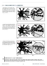
Fig.19
Fig.21
Fig.22
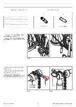
- Insert the link to close into the provided
seats (Fig. 19).
- Lock the link by means of the special
locking device (Z - Fig. 19).
- Check that the tapered tip of the
pusher is in line with the centre of the
bushing ULTRA-LINK 5-CN-RE500 (11s)
/ 5-CN-RE600 (12s) (Fig. 20).
- Screw in the tool to bring the pusher
into contact with the protruding end of
the ULTRA-LINK 5-CN-RE500 (11s) /
5-CN-RE600 (12s) bush, turning it by
about 3⁄4 of a turn and exerting modera-
te force till distorted (Fig. 21).
- The slight protrusion (X) (towards the
external side of the chain) of the small
pin (E) from the link (Fig. 22) is entirely
normal and does not obstruct normal
chain movement.
Fig.23
- Make sure that chain closure does not
present any “harsh points” or links that
do not bend freely (Fig. 23).
Fig.20
Z
F
Lato esterno
della catena
F
Internal side
of the chain
Lato esterno
della catena
E
X
E
X
!
NEVER try to eliminate this pro-
trusion!
NO!
OK!
CHAIN - Rev. 06/ 02-2021
External side
of the chain


