background image

CAMPAGNOLO COMPONENTS - TECHNICAL MANUAL

5

CHAIN - Rev. 06/ 02-2021

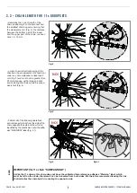
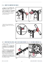
3.3 - CHAIN LENGTH FOR 11s GROUPSETS

H

NO!

Fig.2

Fig.3

Fig.4

• Determine the correct length of the 

chain positioning it on the sprocket and 

the smallest chainring and ensuring that 

the measurement H (Fig. 2), the distance 

between the bottom part of the rocker 

and the upper part of the chain, is about 

circa 10 - 15 mm.

• Perform all of the following operations 

and remove extra links from the side of the 

chain opposite the external link, which is 

identified by the plastic band and the adhe-

sive “WARNING!” label (Fig. 4.1).

• n order to avoid malfunctioning of the 

drivetrain, the measurement H should not 

under any circumstances be less than 3 

mm (Fig. 3) and must not be greater than 

22 mm because, with a large sprocket 

and chainring the chain would be exces-

sively taut (Fig. 4).

!

Unlike the 11s chains, this chain does not have the calibrated hole reference adhesive “Warning” label, which 

must be left on the chain, therefore it can be truncated from both sides. We therefore recommend leaving the link 

that indicates the chain batch, truncating the opposite side.

IMPORTANT (for 11s chain “CAMPAGNOLO”)

NO!

H = 8÷15 mm max

Fig.4.1

Summary of Contents for Ergopower Record 12s

Page 1: ...CAMPAGNOLO COM 12s 11s CHAIN...

Page 2: ...CHAIN Rev 06 02 2021 CAMPAGNOLO COMPONENTS TECHNICAL MANUAL 2 ALWAYS wear protective gloves and glasses while working on the bicycle WARNING...

Page 3: ...t is illustrated as the specific purpose of these instructions is to explain the procedures for using the component The 12s chain is not compatible with 10s and 11s drivetrains Use the 12s chain only...

Page 4: ...ith 48 32 chainring and 11 34 sprocket box follow the indications below accor ding to the frame chainstay length 405 409 mm 108 links 410 415 mm 110 links over 415 mm 112 links For any other crankset...

Page 5: ...he external link which is identified by the plastic band and the adhe sive WARNING label Fig 4 1 n order to avoid malfunctioning of the drivetrain the measurement H should not under any circumstances...

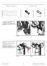
Page 6: ...SERTING THE ULTRA LINK 5 CN RE600 BUSHING 12s 5 CN RE500 BUSHING 11s Remove the plastic band and the adhe sive Warning label To install the closing pin ULTRA LINK 5 CN RE500 11s 5 CN RE600 12s place t...

Page 7: ...crew tool UT CN400 12s UT CN300 11s 12s Fig 10 Position the tool UT CN400 12s UT CN300 11s 12s as shown in Fig 11 UT CN400 UT CN300 X Fit the link to be closed in the relative seats Fig 11 Clamp the l...

Page 8: ...0 1 mm from the inner side of the chain Fig 13 Insert the protruding part of the guide into the hole provided at the base of the tool and split it by bending Fig 14 The terminal part of the split gui...

Page 9: ...LTRA LINK 5 CN RE500 11s 5 CN RE600 12s bush turning it by about 3 4 of a turn and exerting modera te force till distorted Fig 21 The slight protrusion X towards the external side of the chain of the...

Page 10: ...rent manufacturers can damage the chain A damaged chain can break even suddenly and cause accidents injuries and even death WARNING Opening and closing the chain on more than two occasions can result...

Page 11: ...ith water under pressure Pressurized water even from the nozzle of a small garden hose can pass seals and enter into your Campagnolo components damaging them beyond repair Wash your bicycle and Campag...

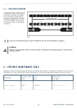
Page 12: ...s longer than 132 60 mm the chain must immediately be replaced 5 PERIODIC MAINTENANCE TABLE Maintenance intervals are strictly approximate and may vary significantly in relation to the intensity and c...

Reviews: