background image

EN

Series DRCS drive for stepper motors

7

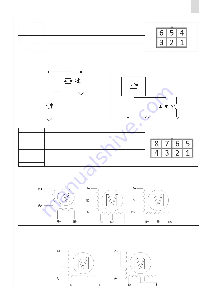
It is possible to connect two proximity switches, one for Homing functionality and another for various functions:

1. Extra stroke sensor

2. Stop movement command (use it for stop the movement before to reach the target position)

Is possible to use both NPN and PNP proximity switches.

Stepper motors can have 4- or 8- wire configurations; the following pictures show these configurations and the connections 

for the most common types of Stepper motors. The motor must be connected to the MOTOR connector:

4-wire motor:

8-wire motor:

As shown in the following picture, the 8-wire motors permit two different connection schemes: series or parallel.

In the series connection scheme, the high-speed torque is lower, but the losses and operating temperature are also reduced. 

With this scheme, it is recommended to decrease the phase current by at least 30%.

In the parallel connection scheme, the torque and speed of the motor follow the torque-speed characteristic curve.

7.3 Proximity connector

7.4 Motor connector

Pin

Signal

Description

1

+24V

+24V power for external proximity (ref. 

GND

)

2

HMG

Input for Homing sensor

3

GND

Common (ref. for pin 1)

4

EXCOM1

Excom1 common (PNP=GND and NPN=+24V DC)

5

GND

Common (ref. for pin 1)

6

OPT

Input for Proximity / external stop (optional)

Pin

Signal

Description

1

B-

Motor phase B negative pole

2

B-

3

A-

Motor phase A negative pole

4

A-

5

B+

Motor phase B positive pole

6

B+

7

A+

Motor phase A positive pole

8

A+

3

4

2

1

EXcom1

Q

R46

2K2 5% 1/2W

3

4

Q

2

1

3

FINE CORSA NPN

+24V

FINE CORSA PNP

2

1

3

2

1

R46

2K2 5% 1/2W

Excom1

3

4

2

1

EXcom1

Q

R46

2K2 5% 1/2W

3

4

Q

2

1

3

FINE CORSA NPN

+24V

FINE CORSA PNP

2

1

3

2

1

R46

2K2 5% 1/2W

Excom1

Summary of Contents for DRCS Series

Page 1: ...Series DRCS drive for Stepper motors EN USE AND MAINTENANCE INSTRUCTIONS...

Page 2: ...lation and start up 5 7 1 DRCS power supply 6 7 2 DRCS encoder 6 7 3 Proximity connector 7 7 4 Motor connector 7 7 5 Brake connector 8 7 6 CANopen connector 8 7 7 25 pin SUB D connector 8 7 8 Inputs 8...

Page 3: ...t safety standards must be observed at all times Never interfere with the machine system before verifying that all working conditions are safe Before installation and maintenance ensure that the envis...

Page 4: ...Quadrants Control position Encoder 100 to 5000 differential pulses revolution Control signal Input 12 opto isolated 24 V DC Control signal Output 6 opto isolated Frequency Input Step and direction inp...

Page 5: ...allow for the recovery or disposal in accordance with current regulations in the country of use Before using the component ensure that the stated specifications and performance features correspond to...

Page 6: ...power is applied to the POWER 48V connector use copper wires with an AWG18 cross section Warning reversing the positive and negative poles can damage the DRCS drive 7 2 DRCS Encoder A differential con...

Page 7: ...r but the losses and operating temperature are also reduced With this scheme it is recommended to decrease the phase current by at least 30 In the parallel connection scheme the torque and speed of th...

Page 8: ...ure starts with the rising edge Digital Inputs IN0 IN6 The digital inputs common pin EXCOM can be connected to either the negative or positive pole of the power supply Every program line set in QSet f...

Page 9: ...d 300V If the load is inductive eg a relay it is necessary to connect a flyback diode If the load is an input module eg a PLC connect a reverse polarity protection device if not already provided by th...

Page 10: ...ends When the motion ends the In Position output POS becomes active the Busy output BSY is deactivated The user must adopt the necessary measures to prevent damage to the system caused by voltage spik...

Page 11: ...of alarms Limitations on use Maintenance Environmental notes 10 11 12 Never exceed the technical specifications stated in the paragraph General characteristics and the Camozzi general catalogue With t...

Page 12: ...camozzi com Technical assistance Product inquiries and requests for support Tel 39 030 3792790 service camozzi com Product Certification Information concerning product certifications EC standards con...

Reviews: