background image

19

Notes

10.1 Connecting the measuring input leads

Connect  the  leads  to  measuring  input  terminals  1  (-)  and  
6 (I+) for DC current measurement or 1 (-) and 11 (U+) for 
DC voltage measurement to suit the particular measurement 
task or application.

10.2 Connecting the measuring output leads

Connect  the  measuring  output  leads  A  to  terminals  
4 (–) and 9 (+).

Note:


Take care that the amplifier’s maximum permissible 
external burden R

ext

 is not exceeded (see Section  

6 “Technical Data”).

10.3 Connecting the power supply leads

Connect  the  power  supply  leads  to  terminals  5  (

–~

)  and  

10 (

+

~

).

A two-pole switch must be included in the supply connection 
where facility for switching SINEAX TV 808 off is desired.

Note: 

An external supply fuse with a rupture capacity  

 20 A must be provided for DC supply voltages  

> 125 V.

11. Configuration

The SINEAX TV 808 unit has to be opened before it can be 
configured (see Section “8. Withdrawing and inserting the 
device”).

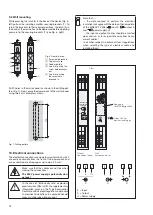
11.1  Type of output signal
 

(voltage or current)

The output can be configured for a voltage or current signal 
by inserting the plug-in jumpers 

“ST 4”

 or 

“ST 3”

 in position 

“U”

 or 

“I”

 (Fig. 8).

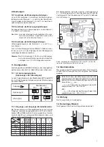
Output

Jumpers

ST 4

ST 3

Current [mA]

Voltage [V]

U I

U I

U I

U I

11.2  Standard input and output ranges

Two of the six plug-in jumpers 

B1

 to 

B6

 are used for selecting 

the standard ranges of the isolating amplifiers. Providing the 
potentiometers “Span” and “Zero” are not moved, changing 
the range has no influence on amplifier accuracy.


4…20

mA

0…20

mA

–20…20

mA

2…10

V

0…10

V

–10…10

V

4…20 mA

B1,B4 B2,B4

B3,B4

B1,B4 B2,B4

B3,B4

0…20 mA

B1,B5

B2,B5

B3,B5

B1,B5 B2,B5

B3,B5

–20…20 mA B1,B6 B2,B6

B3,B6

B1,B6 B2,B6

B3,B6

2…10 V

B1,B4 B2,B4

B3,B4

B1,B4 B2,B4

B3,B4

0…10 V

B1,B5 B2,B5

B3,B5

B1,B5 B2,B5

B3,B5

–10…10 V

B1,B6 B2,B6

B3,B6

B1,B6 B2,B6

B3,B6

The  default  setting  of  the  preferred  versions  ex  stock  is  
0 … 20 mA for input and output, i.e. jumpers are inserted 
in positions B2 and B5 and jumpers ST 4 and ST 3 are in 
position “I”.

��

��

��

B4

B5

B6

U I

U I

ST3

ST4

����

����

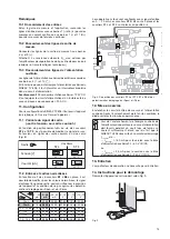
Fig. 8. Position of the jumpers ST 4 and ST 3, B1 to B6 and the 
potentiometers “Span” and “Zero”.

12. Commissioning

Switch on the measuring input and the power supply. The 
green LED lights continuously after switching on.

The power supply unit must be capable of supplying 
a brief current surge when switching on. The instru-
ments presents a low impedance at the instant of 
switching which requires a current I

start 

of …

… I

start


 160 mA for the version with a power supply 

range of 24 – 60 V DC/AC
or
… I

start


 35 mA for the version with a power supply 

range of 85 – 230 V DC/AC

13. Maintenance

No maintenance is required.

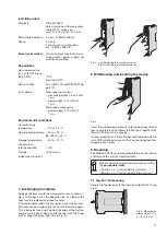
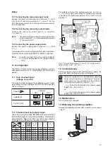
14. Releasing the isolating amplifier

Release the isolating amplifier from a top-hat rail as shown 
in Fig. 9.

ON

Fig. 9

Summary of Contents for SINEAX TV 808-11

Page 1: ...éparateur SINEAX TV 808 11 Operating Instructions Isolating amplifier SINEAX TV 808 11 Camille Bauer AG Aargauerstrasse 7 CH 5610 Wohlen Switzerland Telefon 41 56 618 21 11 Telefax 41 56 618 35 35 e mail info camillebauer com http www camillebauer com TV 808 11 Bdfe 124 446 02 07 06 ...

Page 2: ...Betriebsanleitungmitfolgenden Symbolen markiert Les conseils de sécurité qui doivent impérativement être observés sont marqués des symboles ci contre dans le présent mode d emploi The following symbols in the Operating Instructions indicate safety precautions which must be strictly observed Geräte dürfen nur fachgerecht entsorgt werden Les appareils ne peuvent être éliminés que de façon appropriée...

Page 3: ...gabe Eingangssignale von Ausgangssignalen galvanisch zu tren nen siezuverstärkenund oderineinenanderenPegeloderin eine andere Signalart Strom oder Spannung umzusetzen 5 Übersicht der Funktionselemente Bild 2 zeigt die wichtigsten Teile die im Zusammenhang mit der Befestigung den Elektrischen Anschlüssen und anderen in der Betriebsanleitung beschriebenen Vorgängen behandelt werden 1 Erst lesen dann...

Page 4: ...pannung 12 V Aussenwiderstand Rext max kΩ 12 V IAN mA IAN Ausgangsstromendwert Gleichspannung Standardbereiche 0 10 V 2 10 V 10 V Grenzwerte 0 1 bis 0 10 V 0 2 1 bis 2 10 V 1 0 1 bis 10 0 10 V Bürde 2 kΩ Strombegrenzung bei Rext max Ca 1 1 IAN bei Stromausgang Spannungsbegrenzung bei Rext Ca 13 V Restwelligkeit des Ausgangsstromes 0 5 p p Einstellzeit 50 ms Hilfsenergie H Allstrom Netzteil DC und ...

Page 5: ...f der gegenüberlie genden Seite herausspringt Das eingelegte Frontschild ist austauschbar und steht zum Anbringen von Vermerken zur Verfügung Nach dem Wiedereinlegen des Frontschildes in die Klar sichtabdeckung diese wieder einsetzen Dazu Klarsicht abdeckung zuerst unter die untere Halterung führen und mit Finger Bild 3 rechts durch Druck zum Einrasten bringen Bild 5 Montage auf Hutschiene 35 15 o...

Page 6: ...en 5 1 1 4 2 3 2 1 1 Gehäuse an Wand oder Montagetafel mit 2 Schrauben 4 mm befestigen Löcher nach Bohrplan Bild 7 bohren 120 Bild 7 Bohrplan 10 Elektrische Anschlüsse Zum Anschliessen der elektrischen Leitungen dienen Schraubklemmen die gut zugänglich in der Frontpartie des Gerätes untergebracht sind und sich für Drahtquerschnitte bis max 2 5 mm2 eignen Unbedingt sicher stellen dass die Leitungen...

Page 7: ...bereiche Bei Trennverstärkern mit Standardbereichen lassen sich die Eingangs und oder Ausgangsbereiche mit 2 von 6 Steck brücken B1 bis B6 einstellen Die Genauigkeit des Gerätes wird nicht beeinflusst solange die Potentiometer Zero und Span nicht verstellt werden 4 20 mA 0 20 mA 20 20 mA 2 10 V 0 10 V 10 10 V 4 20 mA B1 B4 B2 B4 B3 B4 B1 B4 B2 B4 B3 B4 0 20 mA B1 B5 B2 B5 B3 B5 B1 B5 B2 B5 B3 B5 20...

Page 8: ...nachgewiesen durch die Einhaltung folgender Normen The above mentioned product has been manufactured according to the regulations of the following European directives proven through compliance with the following standards Nr No Richtlinie Directive 89 336 EWG 89 336 EEC Elektromagnetische Verträglichkeit EMV Richtlinie Electromagnetic compatibility EMC directive EMV EMC Fachgrundnorm Generic Stand...

Page 9: ...ique 4 Description brève L amplificateur de séparation actif SINEAX TV 808 sert à la séparation galvanique de signaux d entrée et de sortie ou à leur amplification et ou à leur transformation en un autre niveau ou genre de signal courant ou tension 5 Illustration des éléments fonctionnels La Fig 2 présente les parties les plus importantes d am plificateur de séparation qui sont décrites ci après et q...

Page 10: ...ourant continu Etendues standards 0 20 mA 4 20 mA 20 mA Valeurs limites 0 1 à 0 20 mA 0 2 1 à 4 20 mA 1 0 1 à 20 0 20 mA Tension de charge 12 V Résistance extérieure Rext max kΩ 12 V IAN mA IAN Valeur finale du courant de sortie Tension continue Etendues standards 0 10 V 2 10 V 10 V Valeurs limites 0 1 à 0 10 V 0 2 1 à 2 10 V 1 0 1 à 10 0 10 V Charge 2 kΩ Limitation de courant en Rext max Env 1 1 I...

Page 11: ...rent Fig 3 à gauche jusqu à ce qu il se libère en haut La plaquette signalétique est interchangeable et sert à des annotations diverses Après mise en place de la plaquette remettre le capot transparent en le glissant d abord dans la gorge inférieure et l encliqueter définitivement par une pression du doigt Fig 3 à droite Fig 5 Montage sur rail à chapeau 35 15 ou 35 7 5 mm SINEAX TV 808 ON SINEAX TV...

Page 12: ...0 V alimentation auxiliaire Pour les appareils en mode de protection à sécuritéintrinsèque EExia IICilfautrespecter les indications contenues dans l attestation de conformité ainsi que les prescriptions nationales pour la réalisation d installations électriques dans des enceintes avec danger d explosions Veuiller en plus que les caractéristiques techniques qui per mettent de résoudre le problème d...

Page 13: ...aliers B1 à B6 en place il est possible de modifier pour les valeurs normalisées le signal d entréeetlesignaldesortie cecisansinfluencerlaprécision de l appareil et à condition de ne pas agir sur les potentio mètres de réglage du Span et du Zéro 4 20 mA 0 20 mA 20 20 mA 2 10 V 0 10 V 10 10 V 4 20 mA B1 B4 B2 B4 B3 B4 B1 B4 B2 B4 B3 B4 0 20 mA B1 B5 B2 B5 B3 B5 B1 B5 B2 B5 B3 B5 20 20 mA B1 B6 B2 B6 ...

Page 14: ...rein nachgewiesen durch die Einhaltung folgender Normen The above mentioned product has been manufactured according to the regulations of the following European directives proven through compliance with the following standards Nr No Richtlinie Directive 89 336 EWG 89 336 EEC Elektromagnetische Verträglichkeit EMV Richtlinie Electromagnetic compatibility EMC directive EMV EMC Fachgrundnorm Generic ...

Page 15: ...AX TV 808 11 Mode d emploi Amplificateur Séparateur SINEAX TV 808 11 Operating Instructions Isolating amplifier SINEAX TV 808 11 3 G O SS EN M ET RA W A TT C A M I LL E BA U ER SINEAX TV 808 ON SINEAX TV 808 ON G O SS EN M ET RA W A TT C A M I LL E BA U ER Isolating amplifier 1 2 Withdrawing handle 2 for withdrawing the device from its housing 2 Front plates 3 for notes 1 Type Examination Certificat...

Page 16: ...easuring output DC current Standard ranges 0 20 mA 4 20 mA 20 mA Limit values 0 1 to 0 20 mA 0 2 1 to 4 20 mA 1 0 1 to 20 0 20 mA Burden voltage 12 V External resistance Rext max kΩ 12 V IAN mA IAN Output circuit full scale value DC voltage Standard ranges 0 10 V 2 10 V 10 V Limit values 0 1 to 0 10 V 0 2 1 to 2 10 V 1 0 1 to 10 0 10 V Burden 2 kΩ Current limiter at Rext max Approx 1 1 IAN for cur...

Page 17: ...n the cover can be replaced and used for notes Afterreplacingthelabelinthetransparentcover thetranspar ent cover can be snapped into the front of the device again This is done by inserting it behind the edge at the bottom and pressing it gently down and to the rear with the finger until it snaps into place right side of Fig 3 Fig 5 Mounting on top hat rail 35 15 or 35 7 5 mm SINEAX TV 808 ON SINEAX...

Page 18: ...e cables are not live when making the connections The 230 V power supply is potentially dan gerous In the case of Intrinsically safe explosion proof versions EEx ia IIC the supplementary information given on the Type Examination Certificateandalsolocalregulationsapplicable to electrical installations in explosion hazard areas must be taken into account Note that the data required to perform the ele...

Page 19: ...B6 are used for selecting the standard ranges of the isolating amplifiers Providing the potentiometers Span and Zero are not moved changing the range has no influence on amplifier accuracy 4 20 mA 0 20 mA 20 20 mA 2 10 V 0 10 V 10 10 V 4 20 mA B1 B4 B2 B4 B3 B4 B1 B4 B2 B4 B3 B4 0 20 mA B1 B5 B2 B5 B3 B5 B1 B5 B2 B5 B3 B5 20 20 mA B1 B6 B2 B6 B3 B6 B1 B6 B2 B6 B3 B6 2 10 V B1 B4 B2 B4 B3 B4 B1 B4 B2 ...

Page 20: ...nachgewiesen durch die Einhaltung folgender Normen The above mentioned product has been manufactured according to the regulations of the following European directives proven through compliance with the following standards Nr No Richtlinie Directive 89 336 EWG 89 336 EEC Elektromagnetische Verträglichkeit EMV Richtlinie Electromagnetic compatibility EMC directive EMV EMC Fachgrundnorm Generic Stand...

Reviews: