17
Installation data
Terminals:
DIN/VDE 0609
Screw terminals with wire guards,
for light PVC wiring and
max. 2
×
0.75 mm
2
or 1
×
2.5 mm
2
Permissible vibrations: 2 g acc. to EN 60 068-2-6
Shock:
3 x 50 g
2 shocks each in 6 directions
acc. to EN 60 068-2-27
Electrical insulation:
All circuits (measuring input / meas-
uring output / power supply) are
electrically insulated
Regulations
Housing protection
(acc. to IEC 529 resp.
EN 60 529):
IP 40
Terminals IP 20
Safe insulation:
Acc. to IEC 1010 and DIN/VDE 106,
part 101
Test voltage:
Measuring input versus:
– measuring output 2.3 kV, 50 Hz,
1 min.
– power supply 3.7 kV, 50 Hz,
1 min.
Measuring output versus:
– power supply 3.7 kV, 50 Hz,
1 min.
Environmental conditions
Commissioning
temperature:
– 10 to + 55 °C
Operating temperature: – 25 to + 55 °C,
Ex – 20
to + 55 °C
Storage temperature:
– 40 to + 70 °C
Annual mean
relative humidity:
≤
75%
Altitude:
2000 m max.
Indoor use statement!
7. Exchanging frontplates
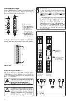
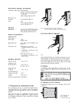
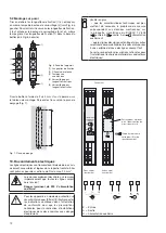
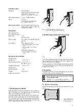
Apply gentle pressure to the transparent cover as shown in
Fig. 3 until pops out on the opposite side. The label in the
cover can be replaced and used for notes.
After replacing the label in the transparent cover, the transpar-
ent cover can be snapped into the front of the device again.
This is done by inserting it behind the edge at the bottom
and pressing it gently down and to the rear with the finger
until it snaps into place (right side of Fig. 3).
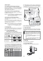
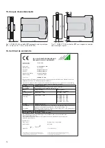
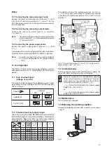
Fig. 5. Mounting on
top-hat rail 35
×
15
or 35
×
7,5 mm.
SINEAX
TV 808
ON
(
SINEAX
TV 808
ON
(
Fig. 3. Left: Removing the transparent cover
Right: Inserting the transparent cover.
8. Withdrawing and inserting the device
SINEAX
TV 808
ON
(
(
(2)
(9)
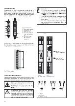
Fig. 4
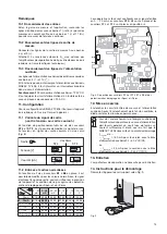
Insert the withdrawing handles (2) into the openings (9) until
they snap into place. Withdraw the front part together with
the main PCB out of the housing.
To reassemble the unit, insert the front part together with the
main PCB into the housing until the swallow-tailed sections
engage in each other.
9. Mounting
The SINEAX TV 808 can be mounted either on a top-hat rail
or directly onto a wall or mounting plate.
Make sur that the ambient temperature stays within
the
permissible limits
:
– 25 and + 55 °C for standard instruments
– 20
and + 55 °C for instruments in
Ex
version!
9.1 Top-hat rail mounting
Simply clip the device onto the top-hat rail (EN 50 022) (see
Fig 5).


