24
14
13
12
11
10
9
8
7
6
3
2
1
5
4
16
15
17 18
I
L1
U
L1
I
L1
I
L2
U
L2
I
L2
I
L3
U
L3
I
L3
N
–
– +
19 20
– + – +
A
B
C
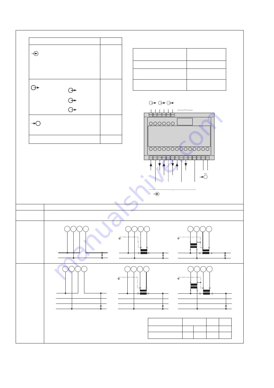
Measuring inputs, acc. to measuring mode
RS 232
Function
Connect.
Measuring input
AC current
IL1
1 / 3
IL2
4 / 6
IL3
7 / 9
AC voltage
UL1
2
UL2
5
UL3
8
N
11
Outputs*)
Analog
–
15
+
16
–
17
+
18
–
19
+
20
Power supply
AC
~
13
~
14
DC
–
13
+
14
RS 232 C interface
Measuring inputs
System /
Application
Terminals
Single-phase
AC system
If power supply is taken from the measured voltage
internal connections are as follow:
Application (system)
Internal connection
Terminal / System
Single-phase AC current
2 / 11 (L1 – N)
4-wire 3-phase
2 / 11 (L1 – N)
symmetric load
All other (apart from
2 / 5
(L1 – L2)
feature 9, lines E, F and J)
A
B
C
4-wire
3-phase
symmetric
load
I: L1
Current transf.
Terminals
2
11
L2
1 3 L2
N
L3
1 3 L3
N
L1
N
11
3
1
L1
N
k
l
K
L
2
11
3
1
L1
N
v
V
u
U
k
l
K
L
2
11
3
1
2
L1
N
11
3
1
L1
N
k
l
K
L
2
11
3
1
L1
v
V
u
U
k
l
K
L
2
11
3
1
2
L2
L3
L2
L3
N
L2
L3
Connect the voltage according to the following
table for current measurement in L2 or L3:
*) M561: Output A
M562: Output A and B
M563: Output A, B and C


