M08627;16/39
- 16 -
10bit
×
1
8bit
×
1
D9
PORTB(1)
PORTA (7)
D8
PORTB(0)
PORTA (6)
D7
PORTA (7)
PORTA (5)
D6
PORTA (6)
PORTA (4)
D5
PORTA (5)
PORTA (3)
D4
PORTA (4)
PORTA (2)
D3
PORTA (3)
PORTA (1)
D2
PORTA (2)
PORTA (0)
D1
PORTA (1)
D0
PORTA (0)
Image data
Output port
assignment
↑
(Default)
Assignment of output data bit
represents the following states:
●
Black and white look inverted at the saturating area.
●
The outline of the saturating area is blurred.
●
The saturating area slightly shifts upward or downward.
●
The brightness value of the saturating area does not reach 1023.
(5-5) Output data gray scale setting
It is selectable any of the following as the output data format in Camera Link STD
・
10 bit gray scale (default)
・
8 bit gray scale
In 10 bit gray scale format, 10 bit image data are output using PORTB(1),
PORTB(0), PORTA(7) to
PORTA(0).
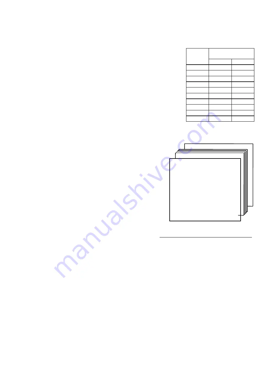
Meanwhile, in 8 bit gray scale format, only the higher-order 8 bits are output via
Camera Link port of PORT(7) to PORT(0) omitting the lower-order 2 bits.
(Refer to right table).
The setting is performed according to the input format of the capture board. The
setting is changed by rewriting the configuration items or “CR” using serial
communication command.
(5-6) Program page setting
The FC series cameras incorporate nonvolatile memories and various operation
mode settings and level settings can be stored in them.
The setting items are stored in the virtual pages (hereinafter referred to as “program pages”)
inside the camera.
This camera has 6 program pages of “A”, “B”, “C”, “D”, “E”
and “F” (right figure).
The camera starts operating according to the various
settings stored in the relevant page when the mode switch is
at any one of the positions from “A” to “F” at the time of
power-on.
The camera starts operating according to the settings stored
in the page “A” when the mode switch is at any position other
than those from “A” to “F” at the time of power-on.
(Note)
The memory area has the independent
configuration area aside from the storage area of program
pages. Common setting items(configuration items) are
stored in this area.
Program page F
Program pages from B to E
Program page A
[Electronic shutter operation mode]
•
Shutter system = Continuous/asynchronous
•
Type of shutter speed = High speed/ low speed
•
Electronic shutter table = Correspondence
relation between shutter switch and shutter
speed
•
Pulse width control = enabled/disabled
•
Rapid dump = enabled/disabled
[Other operation modes]
•
Scanning system = Normal/partial/draft -scan
[Level setting]
•
Gain setting value = (Saved as the internal value)
•
Offset = (Saved as the internal value)
Fig. 5-2 Conceptual diagram of program page


