+
-
,
.
#,3%.3
:,
/03%.3
-/4/2&53%
!&
/.
!##&53%!&
,).%&53%
!&
/0%.
/0#,
!&
66 6
- .
%
%.#2!$)/
6
6
!#4
3,/73%.3
#"/
!2$&53%M!&
,4
,
,4
.
2
3
4
19
5
7
8
9
10
11
1
6
18
12
13 14
15
16
17
24
20
22
25
21
23
Pa
g.
1111
- C
od
ic
e m
an
ua
le:
11
9
E
T
9
7
11
9
E
T
9
7
ver
.
33
0
5
/2
01
4
©
C
A
M
E c
ancel
li au
tomatici
s.p
.a
. -
I dati
e
le
in
for
m
az
ioni
in
dic
ate
in
ques
to
manuale
s
ono
da
r
itener
si
sus
cet
tibi
li d
i m
od
ifi
ca
in
q
ua
ls
ia
si m
om
en
to e s
en
za o
bb
lig
o d
i p
re
av
vi
so d
a p
ar
te d
i C
A
M
E c
an
ce
lli a
ut
om
at
ic
i s
.p.
a.
IT
ALIANO
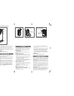
6.2 Componenti principali
1. Fusibile di linea 1.6 A
2. Spazio per batterie d’emergenza
3. Motoriduttore
4. Trasformatore
5. Morsettiera collegamento trasformatore
6. Fusibile motore 8 A
7. Morsettiera collegamento motoriduttore
8. Morsettiera collegamento encoder
9. Led segnalazione radio e programmazione encoder
10. Pulsante di memorizzazione codice radio
11. Trimmer SLOW.SENS: regolazione della sensibilità amperometri-
ca in rallentamento
12. Trimmer A.C.T.: regolazione tempo chiusura automatica
13. Trimmer CL.SENS.: regolazione della sensibilità amperometrica
in chiusura
14. Trimmer OP.SENS: regolazione della sensibilità amperometrica
in apertura
15. Pulsanti di comando per la regolazione dei finecorsa
16. Selettore funzioni
17. Lampada di servizio
18. Fusibile accessori 3,15 A
19. Fusibile centralina 315 mA
20. Morsettiera per collegamento accessori e dispositivi di comando
21. Innesto scheda di radiofrequenza AF
22. Foro per ingresso cavi elettrici
23. Led di segnalazione presenza tensione
24. Morsettiera di alimentazione
25. Morsettiera per antenna radio
6.3 Collegamenti elettrici
Alimentazione e accessori
Morsetti per l’alimentazione degli accessori:
- a 24 V AC normalmente;
- a 24 V DC quando intervengono le batterie d’emergenza;
Potenza complessiva consentita: 40 W.
Capocorda a occhiello per collegamento a terra.
Alimentazione
a 230 V AC -
50 / 60 Hz
Attenzione! Prima di intervenire sull’apparecchiatura, togliere la
tensione di linea e scollegare le batterie di emergenza (se presenti).
Summary of Contents for V900E
Page 3: ......
Page 27: ...INSTALLATION MANUAL V900E OPERATOR FOR OVERHEAD AND SECTIONAL DOORS English EN 119ET97EN ...
Page 29: ......
Page 55: ......
Page 81: ......