#
/
-
2ALLENTAM
6ELOCITÍ
-AX
-AX-ED
-IN
-IN
$)3
/.
.
-
04
&
&#
&!
.
,
,
,4
%
#
#
'.$
48
28
9
8
7
10
11
1
2
12
13
3
6
5
4
14
18
.
-
04 & &# &!
COM
NC
NC
COM
16
15
17
Pa
g.
1
5
15
-
Ma
n
u
al
c
od
e:
11
9
G
U
5
5
11
9
G
U
5
5
ve
r.
0
.2
0.
2
0
3
/2
0
10
© C
A
M
E c
an
ce
lli
auto
m
ati
ci
s.p.a. -
Th
e d
ata a
n
d i
nf
or
m
ati
on r
ep
orte
d i
n th
is
in
sta
lla
tio
n m
an
u
al
a
re s
u
sc
ep
tib
le to c
h
an
g
e at a
ny ti
m
e a
n
d w
ith
ou
t o
b
lig
ati
on
o
n C
A
M
E c
an
ce
lli
auto
m
ati
ci
s.p.a. to n
otify u
se
rs.
ENGLISH
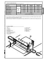
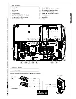
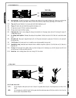
6.1 Main components
1 -
Accessories fuse
2 -
Line fuse
3 -
Control unit fuse
4 -
Motor fuse
5 -
Accessories terminals
6 -
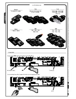
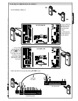
Radio-frequency card input (see table page 19)
7 -
SENS Trimmer: adjusts amperometric sensitivity
8 -
TCA Trimmer: adjusts automatic closing time
9 -
“Function selector” Dip switch
10 - Code storing button
11 - Signalling LEDs for radio codes/automatic closing
12 - Adjustment connectors for deceleration speed
13 - Connectors for LB38 battery charger
14 - Command-type selection jumper for button 2-7
15 - Transformer
16 - Power supply Terminals
17 - Motor Terminals
18 - Endstop Terminals
6.2 Electrical connections
Motor 24V (d.c.)
Gearmotor, endstop
Closing microswitch
Orange
Orange
White
Red
Blue
Brown
Opening micros-
witch
Description of required electrical connections. When installing on the right side, see page 7.
Wh
ite
Red
Blac
k
Br
own
Blue
Br
own

