background image

45°

45°

200 max

80 max

p.


11

 - M

anu

al 

F

A

0

111

7

-E

N

 - 0

3

/2

0

18 - © C

A

M

E S

.p

.A

. - T

ransla

tio

n of t

he o

riginal inst

ru

ct

io

ns

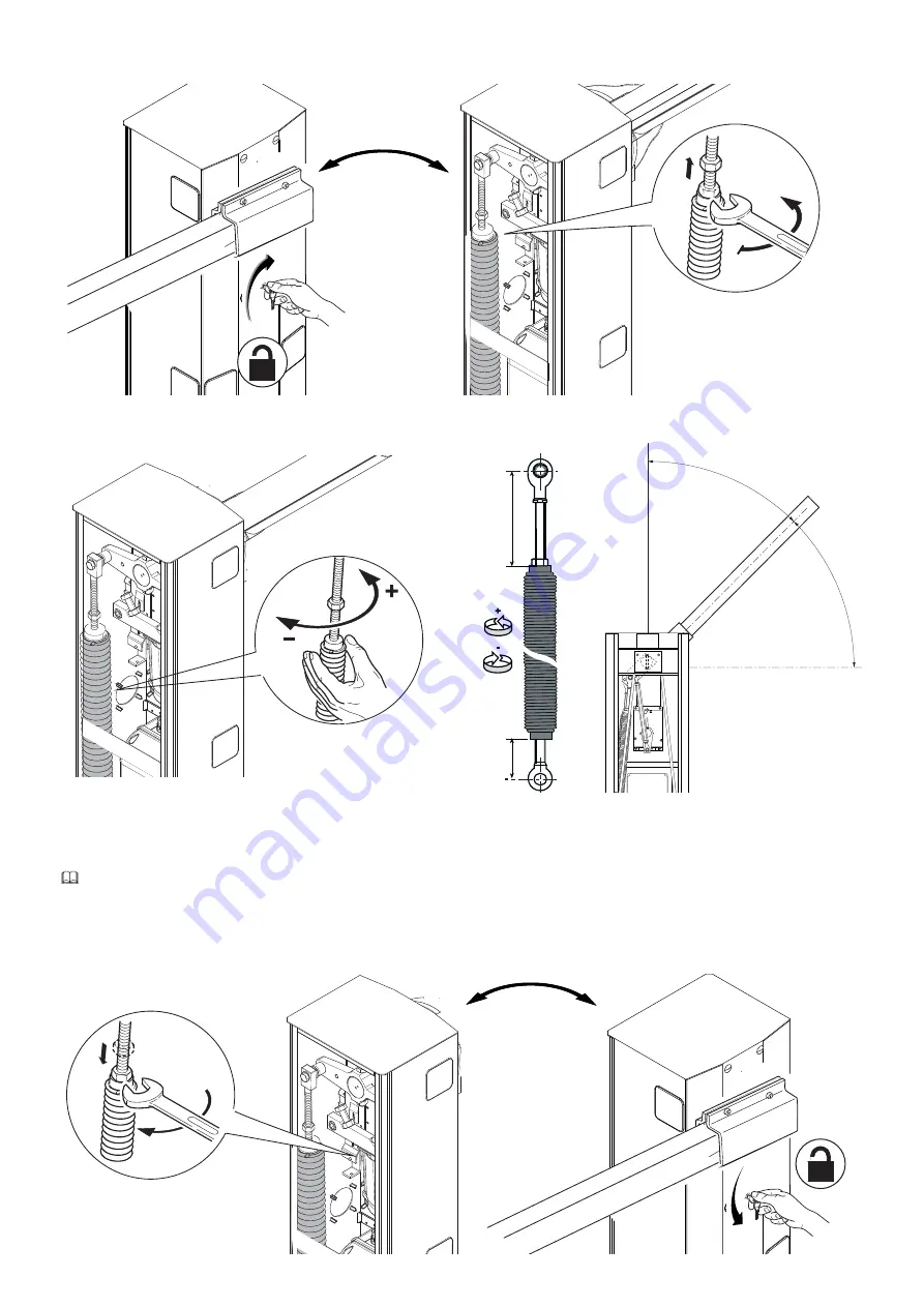
Manually turn the spring to increase or reduce the traction. The boom should stabilize at 45°.

To precision balance the barrier, fi rst release the gear motor and loosen the rod nut.

Fit the nut to fasten the rod to the spring and tighten it.
Lock the gear motor once again.

 Check the proper working state of the spring. 

With the boom raised vertically the spring is not taut.
With the boom lowered horizontally the spring is taut.

Caution! After performing balancing procedures, LUBRICATE THE SPRINGS WITH SPRAY GREASE!

Summary of Contents for G4001

Page 1: ...IT Italiano EN English FR Fran ais RU FA01117M04 Barriera automatica serie GARD G4000 G4001 G4000N MANUALE DI INSTALLAZIONE...

Page 2: ...2 1...

Page 3: ...area di movimento dell asta oppure dove non possono essere raggiunti dall esterno attraverso la barriera A meno che non sia previsto l azionamento a chiave ad es selettore a tastiera selettore a chia...

Page 4: ...ESENTANO UNA BARRIERA SINISTRA DESTINAZIONE D USO La barriera automatica stata progettata per l utilizzo in parcheggi privati o pubblici Ogni installazione e uso difformi da quanto indicato nel seguen...

Page 5: ...di bilanciamento 7 Fermi meccanici 8 Finecorsa 9 Quadro comando 10 Zanche di ancoraggio IMPIANTO TIPO 1 Barriera 2 Lampeggiatore 3 Asta 4 Strisce rosse rifrangenti 5 Fotocellule 6 Supporto per fotoce...

Page 6: ...zzare cavi tipo FROR 20 22 II conformi alla EN 50267 2 1 CEI Per il collegamento dell antenna utilizzare cavo tipo RG58 consigliato fino a 5 m Qualora i cavi abbiano lunghezza diversa rispetto a quant...

Page 7: ...zanche di ancoraggio alla piastra di fissaggio Riempire di terra lo scavo attorno al blocco di cemento Togliere i dadi e le rondelle dalle viti Inserire i cavi elettrici nei tubi fino a farli uscire d...

Page 8: ...are delle attrezzature di sollevamento per trasportare e posizionare la barriera Il montaggio deve essere eseguito da almeno due persone Durante le fasi di premontaggio e fissaggio la barriera potrebb...

Page 9: ...i originali Posizionare il copri attacco asta alla piastra dell albero motore con una sola vite lasciandola allentata Inserire l asta nel copri attacco asta Posizionare l asta in verticale e ssarla co...

Page 10: ...VERTENZE 001G02802 Non pu essere utilizzato per le barriere con asta dotata di rastrelliera 001G0465 o appoggio mobile 001G02808 001G02807 Da utilizzare OBBLIGATORIAMENTE per passaggio utile superiore...

Page 11: ...in verticale la molla non in tensione Con asta posizionata in orizzontale la molla in tensione Attenzione Al termine delle operazioni di bilanciamento LUBRIFICARE LE MOLLE CON GRASSO SPRAY Per bilanc...

Page 12: ...e connessioni sono protette da fusibili rapidi DESCRIZIONE DELLE PARTI 1 Fusibile accessori 2 Fusibile di linea 3 Fusibile scheda 4 Fusibile motore 5 Morsettiera per dispositivi di comando e sicurezza...

Page 13: ...AMENTO DI FABBRICA Il motoriduttore gi collegato Per l installazione a destra della barriera richiedere la documentazione al vostro rivenditore di fiducia o contattare la sede Came del vostro Paese ww...

Page 14: ...comando contatto NO Attenzione in modalit AZIONE MANTENUTA obbligatorio collegare il dispositivo di comando su 2 4 Posizionare il jumper come in figura Funzione SOLO APRE o APRE CHIUDE INVERSIONE pas...

Page 15: ...ule C1 riapertura durante la chiusura In fase di chiusura dell asta l apertura del contatto provoca l inversione del movimento fino alla completa apertura Se non utilizzato cortocircuitare il contatto...

Page 16: ...i apertura Le manovre di apertura e chiusura della barriera vanno eseguite con lo sportello d ispezione chiuso In apertura sbloccare il motoriduttore abbassare l asta aprire lo sportello d ispezione e...

Page 17: ...nto dell asta 4 ON AZIONE MANTENUTA 4 OFF disattivata 5 ON PRE LAMPEGGIO in apertura e in chiusura durata pre lampeggio 5 secondi 5 OFF disattivata 6 ON RILEVAZIONE OSTACOLO a motore fermo 6 OFF disat...

Page 18: ...3S o AF868 sul connettore della scheda elettronica Prima di inserire la scheda AF OBBLIGATORIO TOGLIERE LA TENSIONE DI LINEA e se presenti scollegare le batterie Tenere premuto il tasto di programmazi...

Page 19: ...Rosso Per regolare la velocit di marcia spostare il faston A su Min Med o Max Per regolare la velocit di rallentamento spostare il faston B su Min o Max OPERAZIONI FINALI Terminati i collegamenti elet...

Page 20: ...2 1 3 4 5 6 7 8 9 1 0 0 R a l l V e l 7 4 Z L 3 7 C O N T R O L P A N E L B A l i n e f u s e m o t o r f u s e a c c e s s o r i e s f u s e MASTER MASTER SLAVE Pag 20 Manuale FA01117 IT 03 2018 CAME...

Page 21: ...i NC sono aperti La barriera non effettua la chiusura automatica 11 12 13 6 Disattivare la funzione MASTER SLAVE La barriera non funziona con il trasmettitore 2 14 16 7 Verificare la bilanciatura dell...

Page 22: ...ficolt semplicemente effettuando la raccolta differenziata per il riciclaggio Prima di procedere sempre opportuno verificare le normative specifiche vigenti nel luogo d installazione NON DISPERDERE NE...

Page 23: ...Pag 23 Manuale FA01117 IT 03 2018 CAME S p A Traduzione delle istruzioni originali Pag 23 Manuale FA01117 IT 03 2018 CAME S p A Istruzioni originali...

Page 24: ...39 0422 4940 fax 39 0422 4941 Manuale FA01117 IT 03 2018 CAME S p A Traduzione delle istruzioni originali I contenuti del manuale sono da ritenersi suscettibili di modifica in qualsiasi momento senza...

Page 25: ...Automatic barrier GARD series G4000 G4001 G4000N INSTALLATION MANUAL English FA01117 EN...

Page 26: ...2 1...

Page 27: ...Fit in plain sight the machine s ID plate when the installation is complete All command and control devices must be installed at least 1 85 m from the boom s operating perimeter or where they are out...

Page 28: ...BARRIERS WHEN ORDERING THE ILLUSTRATIONS IN THIS MANUAL ARE ALL FOR LEFT HAND BARRIERS INTENDED USE The automatic barrier is designed for private and public parking facilities Do not install of use t...

Page 29: ...ht 3 Boom 4 Red reflective strips 5 Photocells 6 Photocell brace 7 Photocells post 8 Fixed rest 9 Control device keypad magnetic key transponder etc 10 Control device post 11 Magnetic coils DESCRIPTIO...

Page 30: ...conduits for the electric cables to pass through making sure they are protected from any mechanical damage CABLE TYPES AND MINIMUM THICKNESSES Connection Cable length 20 m 20 30 m Input voltage for 23...

Page 31: ...at least 24 hrs for the concrete to solidify Remove the foundation frame Fill the hole with earth around the concrete block Remove the nut and washer from the bolts Fit the electric cables into the t...

Page 32: ...least two people During the initial mounting and fastening the barrier may be unstable and could tip over Then be careful to no rest against it until it is completely and securely fastened Fit the cus...

Page 33: ...18 CAME S p A Translation of the original instructions Raise the boom vertically and tighten the remaining bolts Fit the boom brace cover to the drive shaft plate use only one bolt and leave it loosen...

Page 34: ...and skirt or swing leg WARNINGS The 001G02802 cannot be used on barriers fitted with the 001G0465 skirt or 001G02808 swing rest The 001G02807 MUST be used with passage widths exceeding 3 m The 001G04...

Page 35: ...sion balance the barrier rst release the gear motor and loosen the rod nut Fit the nut to fasten the rod to the spring and tighten it Lock the gear motor once again Check the proper working state of t...

Page 36: ...rminals for control and safety devices 6 AF card slot 7 SENS trimmer 8 ACT Trimmer 9 DIP SWITCH 10 Programming button 11 Programming warning LED 12 Speed and slow down adjusting connectors 13 Battery...

Page 37: ...can power up the 24 V DC accessories by using buffer batteries 230 V AC 50 60 Hz POWER SUPPLY FACTORY WIRING The gear motor is already connected To install the barrier on the right side ask your local...

Page 38: ...h 3 ONLY OPEN or OPEN CLOSED INVERT step step function from control device NO contact see DIP switch 2 Set the jumper as shown in the figure ONLY CLOSE function from control device NO contact Warning...

Page 39: ...ut for safety accessories such as photocells C1 reopening while closing When the boom is closing opening the contact causes its movement to invert until fully opened If unused shortcircuit contact 2 C...

Page 40: ...CH POINTS Close the inspection hatch and power up the system Move the boom the check that it is parallel to the road surface when closed and at about 89 when open The barrier s opening and closing man...

Page 41: ...1 ON AUTOMATIC CLOSING set 1 to OFF to deactivate it 2 ON ONLY OPEN from button 2 7 and or from transmitter with AF card fitted 2 OFF OPEN CLOSE INVERT from the button on 2 7 and or from a transmitte...

Page 42: ...ard The programming LED flashesq Press any key on the transmitter you want to memorize The LED stays on to indicate that memorization has been successfulr Connect the RG58 cable antenna cable to the c...

Page 43: ...PEED FINAL OPERATIONS Once you ve finished with the electrical connections and powered up the system replace the inspection hatch n and lock it by using the key o To adjust the slow down speed move fa...

Page 44: ...l e n t i s s e m e n t D A b e n c a e l h e m r a e c i n 2 1 3 4 5 6 7 8 9 1 0 0 R a l l V e l 7 4 Z L 3 7 C O N T R O L P A N E L B A l i n e f u s e m o t o r f u s e a c c e s s o r i e s f u s...

Page 45: ...ER SLAVE function The barrier does not work with the transmitter 2 14 16 7 Check the boom s balancing and spring tautness The boom s direction of travel is inverted 7 18 8 Deactivate the OBSTRUCTION D...

Page 46: ...uld be disposed of as solid household waste and simply separated from other waste for recycling Always make sure you comply with local laws before dismantling and disposing of the product DISPOSE OF R...

Page 47: ...p 23 Manual FA01117 EN 03 2018 CAME S p A Translation of the original instructions...

Page 48: ...Libert 15 31030 Dosson di Casier Treviso Italy tel 39 0422 4940 fax 39 0422 4941 Manual FA01117 EN 03 2018 CAME S p A Translation of the original instructions The contents of this manual may change at...

Page 49: ...Barri re automatique s rie GARD G4000 G4001 G4000N MANUEL D INSTALLATION Fran ais FA01117 FR...

Page 50: ...2 1...

Page 51: ...ur nal par le biais de pictogrammes sp ci ques bien en vue qu il faudra lui expliquer Au terme de l installation appliquer la plaque d identi cation dans une position bien en vue Tous les dispositifs...

Page 52: ...UTES LES ILLUSTRATIONS DE CE MANUEL REPR SENTENT UNE BARRI RE VERSION GAUCHE UTILISATION PR VUE La barri re automatique a t con ue pour une utilisation dans des parkings priv s ou publics Toute instal...

Page 53: ...cellules 6 Support pour photocellules 7 Colonne pour photocellules 8 Support fixe 9 Dispositif de commande clavier cl magn tique badge etc 10 Potelet pour dispositif de commande 11 D tecteur de masses...

Page 54: ...afin de les prot ger contre la d t rioration m canique TYPE DE C BLES ET PAISSEURS MINIMUM Connexion Longueur c ble 20 m 20 30 m Alimentation carte lectronique 230 VAC 1P N PE 3G x 1 5 mm 2 3G x 2 5...

Page 55: ...tendre que le tout se solidifie pendant au moins 24 heures Enlever le coffrage Remplir de terre le trou autour du bloc de ciment Enlever les crous et les rondelles des vis Introduire les c bles lectri...

Page 56: ...ontage et de fixation la barri re pourrait tre instable et pr senter un risque de renversement Il convient par cons quent de ne pas s y appuyer tant qu elle n est pas compl tement fix e Introduire la...

Page 57: ...on des instructions originales Positionner la lisse verticalement et la xer l aide des autres vis Positionner le cache plaque de xation de la lisse sur la plaque de l arbre moteur l aide d une seule v...

Page 58: ...ISSEMENTS 001G02802 Ne peut tre utilis sur les barri res avec lisse quip e de tablier 001G0465 ou support mobile 001G02808 001G02807 utiliser OBLIGATOIREMENT en cas de passage sup rieur 3 m 001G0465 0...

Page 59: ...se d bloquer le motor ducteur et desserrer l crou de xation du tirant Positionner l crou de xation du tirant au ressort et le bloquer Rebloquer le motor ducteur Contr ler le bon fonctionnement du ress...

Page 60: ...NS 8 Trimmer ACT 9 Micro interrupteurs DIP 10 Bouton de programmation 11 Voyant de signalisation de la programmation 12 Connecteurs de r glage pour la vitesse et le ralentissement 13 Connecteurs pour...

Page 61: ...une batterie tampon 230 VAC 50 60 Hz ALIMENTATION CONNEXION PAR D FAUT Le motor ducteur est d j connect Pour une installation de la barri re droite demandez la documentation correspondante votre reve...

Page 62: ...TURE INVERSION pas pas depuis un dispositif de commande contact NO voir DIP 2 Positionner le cavalier comme indiqu sur la figure Fonction FERMETURE UNIQUEMENT depuis un dispositif de commande contact...

Page 63: ...ouverture durant la fermeture Durant la phase de fermeture de la lisse l ouverture du contact provoque l inversion du mouvement jusqu l ouverture totale S il n est pas utilis court circuiter le contac...

Page 64: ...tallation sous tension Actionner la lisse pour s assurer qu elle est bien parall le la surface de la route en position de fermeture et environ 89 en position d ouverture Les man uvres d ouverture et d...

Page 65: ...eurs DIP Description des fonctions 1 ON FERMETURE AUTOMATIQUE 1 OFF d sactiv e 2 ON OUVERTURE UNIQUEMENT depuis le bouton sur 2 7 et ou depuis l metteur avec carte AF activ e 2 OFF OUVERTURE FERMETURE...

Page 66: ...e voyant de programmation clignote q Appuyer sur une des touches de l metteur m moriser Le voyant restera allum pour signaler l ex cution effective de la m morisation r Connecter le c ble RG58 de l an...

Page 67: ...OP RATIONS FINALES Au terme des branchements lectriques et de la mise en fonction remettre la porte de visite en place net la verrouiller o Pour r gler la vitesse de ralentissement d placer la cosse...

Page 68: ...e m r a e c i n 2 1 3 4 5 6 7 8 9 1 0 0 R a l l V e l 7 4 Z L 3 7 C O N T R O L P A N E L B A l i n e f u s e m o t o r f u s e a c c e s s o r i e s f u s e MASTER MASTER SLAVE Page 20 Manuel FA0111...

Page 69: ...e pas avec l metteur 2 14 16 7 Contr ler l quilibrage de la lisse et la tension des ressorts La lisse inverse le sens de la marche 7 18 8 D sactiver la fonction D TECTION OBSTACLE Un seul metteur fonc...

Page 70: ...ans aucune difficult en proc dant tout simplement la collecte diff renci e pour le recyclage Avant d effectuer ces op rations il est toujours recommand de v rifier les normes sp cifiques en vigueur su...

Page 71: ...Page 23 Manuel FA01117 FR 03 2018 CAME S p A Traduction des instructions originales...

Page 72: ...0 Dosson di Casier Treviso Italy tel 39 0422 4940 fax 39 0422 4941 Manuel FA01117 FR 03 2018 CAME S p A Traduction des instructions originales Le contenu de ce manuel est susceptible de subir des modi...

Page 73: ...GARD G4000 G4001 G4000N FA01117 RU...

Page 74: ...2 1...

Page 75: ...CAM E G4000 3 FA01117 RU 03 2018 CAME S p A CAME S p A 2006 42 CE 2006 42 CE 2006 42 CE 20 1 85 1 5 2006 42 CE III 3 c EN 12453 EN 12445...

Page 76: ...260 265 220 270 1007 884 4 FA01117 RU 03 2018 CAME S p A G4000 G4001 G4000N 4 G4000 G4001 G4000N IP 54 50 60 230 24 1 3 230 15 24 300 200 2 6 C 20 55 i 1 202 I 47...

Page 77: ...3 4 8 5 2 6 7 1 9 CAM E 1 4 3 10 8 7 7 2 6 11 9 5 5 5 FA01117 RU 03 2018 CAME S p A 1 2 3 4 5 6 7 8 9 10 11 1 2 3 4 5 6 7 8 9 10 10...

Page 78: ...6 FA01117 RU 03 2018 CAME S p A 20 20 30 230 1P N PE 3G x 1 5 2 3G x 2 5 2 2 x 0 5 2 2 x 0 5 2 2 x 0 5 2 4 x 0 5 2 230 H05RN F 60245 IEC 57 IEC H05VV F 60227 IEC 53 IEC 48 FROR 20 22 II EN 50267 2 1 C...

Page 79: ...M12 UNI5588 M12x40 UNI 5739 7 FA01117 RU 03 2018 CAME S p A 24 600...

Page 80: ...M12 UNI 5588 8 FA01117 RU 03 2018 CAME S p A CAME www came com...

Page 81: ...UNI 5931 M8x20 9 FA01117 RU 03 2018 CAME S p A...

Page 82: ...A B 10 FA01117 RU 03 2018 CAME S p A L 2 5 2 5 3 5 3 5 4 A A B 001G0460 A B 001G0465 001G02808 B 001G02802 001G0465 001G02808 001G02807 3 001G0465 001G02808...

Page 83: ...45 4 5 200 max 80 max 11 FA01117 RU 03 2018 CAME S p A 45...

Page 84: ...3 4 5 6 7 8 9 10 N M PT F FC FA N L L27 L1T E 10 11 1 2 3 5 7 C1 C5 GND TX RX 9 8 7 10 11 1 2 12 13 3 6 5 4 14 18 16 15 17 Blu 12 FA01117 RU 03 2018 CAME S p A ZL38 3 15 A 630 A 10 A 2 A 1 2 3 4 5 6...

Page 85: ...ON 2 1 E 10 11 1 2 3 5 7 C1 C5 GND TX RX 04 COM NC NC COM 13 FA01117 RU 03 2018 CAME S p A 24 24 40 24 230 50 60 CAME www came com 230...

Page 86: ...CAME 14 FA01117 RU 03 2018 CAME S p A 24 3 24 32 DIP 3 2 3 DIP 9 2 4 DIP 2...

Page 87: ...RX TX RX TX DIR DELTA S DELTA 15 FA01117 RU 03 2018 CAME S p A C1 C5 C1 2 1 5 DIP 8 ON...

Page 88: ...1 8 9 1 8 9 n o n o 16 FA01117 RU 03 2018 CAME S p A n o 89 n o...

Page 89: ...2 3 5 7 C1 C5 GND TX RX ON OFF ON 2 1 3 4 5 6 7 8 9 10 N M PT F FC FA N L L27 L1T E 10 11 1 2 3 5 7 C1 C5 GND TX RX 3 3 4 17 FA01117 RU 03 2018 CAME S p A SENS A C T 1 120 DIP 1 1 OFF 2 2 7 AF 2 2 7...

Page 90: ...n TOP TAM o 04 48 28 p 04 4 28 q ON 2 1 3 4 5 6 7 8 9 10 PT F FC FA TX RX r 18 FA01117 RU 03 2018 CAME S p A AF43S AF AF43S AF868 PROG PROG q r RG58 n TOP TAM 433 92 AF43S o AF AF43S AF868 p AF...

Page 91: ...n o 4 C O M Max Max Med Min Min DIS 27370 A B 19 FA01117 RU 03 2018 CAME S p A n o B Min Med Max A Min Med Max Min Med Max COM...

Page 92: ...9 10 0 Rall Vel 7 4 ZL 37 CONTROL PANEL B A line fuse motor fuse accessories fuse CAME O C M M a x M e d M i n M i n M a x V e l o c i t S p e e d G e s c h w V i t e s s e V e l o c i d a d R a l l e...

Page 93: ...l i n e f u s e m o t o r f u s e a c c e s s o r i e s f u s e C A M E O C M Max Med Min Min Max Velocit Speed Geschw Vitesse Velocidad Rallentamento Deceleration Geschw Ralentissement D Ab en c a e...

Page 94: ...22 FA01117 RU 03 2018 CAME S p A CAME S p A UNI EN ISO 14001...

Page 95: ...23 FA01117 RU 03 2018 CAME S p A...

Page 96: ...CAME S p A Via Martiri Della Libert 15 31030 Dosson di Casier Treviso Italy tel 39 0422 4940 fax 39 0422 4941 FA01117 RU 03 2018 CAME S p A...

Reviews: