background image

5

T

h

e d

at

a a

n

d i

n

fo

rm

at

io

n p

rovi

d

ed

 i

n

 t

h

is

 m

an

u

al

 a

re to b

e c

o

n

si

d

er

ed

 s

u

sc

ep

ti

b

le to c

h

an

g

e a

t a

n

y t

im

e w

it

h

o

u

t w

ar

n

in

g

, by CAM

E c

an

ce

ll

i a

u

to

m

at

ic

i S

.p

.A

.

ENGLISH

28

#!-

%

#!-%

48

2

1

7

3

4

5

6

8

9

10

11

12

13

14

15

16

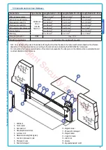
N.B.:  An evaluation of the size of the cables with lengths other than the data in the table must be made based on the effective 
absorption of the connected devices, according to the instructions indicated by the CEI EN 60204-1 standards.
For connections that require several loads on the same line (sequential), the size given on the table must be re-evaluated based 
on actual absorption and distances.

5.3 Cable list and minimun thickness

Connections

Type of cable

Length of cable 1 < 10 m Length of cable 10 < 20 m  Length of cable 20 < 30 m

230V 2F power supply

FROR CEI 

20-22 

CEI EN 

50267-2-1

3G x 1,5 mm

2

3G x 2,5 mm

2

3G x 4 mm

2

24V motor power supply

2 x 1 mm

2

2 x 1,5 mm

2

2 x 2,5 mm

2

Photoelectric cells TX

2 x 0,5 mm

2

2 x 0.5 mm

2

2 x 0,5 mm

2

Photoelectric cells RX

4 x 0,5 mm

2

4 x 0,5 mm

2

4 x 0,5 mm

2

24V power supply accessory

2 x 0,5 mm

2

2 x 0,5 mm

2

2 x 1 mm

2

Control button

2 x 0,5 mm

2

2 x 0,5 mm

2

2 x 0,5 mm

2

End stop

3 x 0,5 mm

2

3 x 1 mm

2

3 x 1,5 mm

2

Antenna connection

RG58

max. 10 m

Metallic mass detector 

(see documents provided with product)


1 -   GARD unit


2 -


  Control panel 


3 -   Aluminium bar


4 -   Red phosphorescent strips


5 -   Luminous cord


6 -   Movement-indicating flashing lamp

 7 -   Column for photoelectric cells
 8 -   Photoelectric cells
 9 -   Fixed barrier support

10 -  Magnetic sensor
11 -  Photoelectric cell support
12 -  Magnetic reader
13 -  Column for reader
14 - Joint for rod
15 - Antenne
16 - Key-operated selector switch

Intelligent Security & Fire Ltd.

Summary of Contents for G2080I

Page 1: ...AUTOMATION FOR STREET BARRIERS INSTALLATION MANUAL GARD 8 SERIES G2080 G2080I I n t e l l i g e n t S e c u r i t y F i r e L t d...

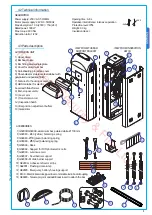
Page 2: ...r accesses of over 3 6m 003 ZL38 Electric board designed to accommodate radio board coupling 002 LB38 Board for the connection of three 12V 6Ah emergency batteries The following accessories are option...

Page 3: ...low balancing spring 3 G04060 50 green balancing spring 4 G06080 55 red balancing spring 5 G02806 Rack 6 G02802 Support for DIR photoelectric cells 7 G02803 Luminous cord 8 G02807 Fixed barrier suppor...

Page 4: ...t continuity are allowed as long as they include additional insulation with respect to other internal drive parts Install suitable tubes and ducts for electric cable passage to guarantee protection ag...

Page 5: ...le 20 30 m 230V 2F power supply FROR CEI 20 22 CEI EN 50267 2 1 3G x 1 5 mm2 3G x 2 5 mm2 3G x 4 mm2 24V motor power supply 2 x 1 mm2 2 x 1 5 mm2 2 x 2 5 mm2 Photoelectric cells TX 2 x 0 5 mm2 2 x 0 5...

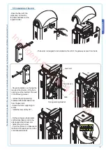
Page 6: ...e and prepare sheath tubes from the branch pit for the connections Remove the nuts and washers from the threaded screws position the cabinet on the base in correspondence with the 4 threaded screws an...

Page 7: ...opening must be inverted Proceed in the following manner remove the spring securing bracket and the transmission rod from the lever arm loosen the motor support grub screw rotate the lever arm by 90 F...

Page 8: ...ut in one UNI 5931 M8x20 screw without tightening it to facilitate bar assembly UNI5931 M8x20 UNI5931 M8x12 Insert it in the bar s conduit a procedure that should be carried out on both sides Insert t...

Page 9: ...age clearance lamp m 2 2 5 3 3 5 4 4 5 5 5 5 6 6 5 7 7 6 By Bare bar we mean a bar complete with the transparent slot cover and end plug 400 mm UNI6954 3 9x19x12 Prior to bar balancing select a suitab...

Page 10: ...osition the bar vertically and then refasten the gearmotor Hook the tie rod to the anchoring racket Perform the same procedure if there is a second screw Insert the UNI5739 M12X70 screw into the sprin...

Page 11: ...te make sure the spring functions properly the spring is loose when the bar is in the vertical position at rest the spring is tight when the bar is in the horizontal position tense 5 7 Electric board...

Page 12: ...total stop 5 8 End stop adjustment Power up the electric board carry out a series of steps to make sure of the bar s correct opening and closing positions and then if necessary proceed to the adjustm...

Page 13: ...ci S p A ENGLISH After bar opening and closing adjustment tighten the locking nuts under the dampers After making adjustments and settings from the control panel put the container lid in place and sec...

Page 14: ...atch with the key and The unit opens but does not close 4 7 10 2 Disable steady movement with dipswitch The unit shuts but does not open 7 9 3 Check power supply and fuses No automatic closure 11 12 1...

Page 15: ...d given to qualified service companies for proper disposal Prior to disposal it is always advisable to check specific regulations in force in the place of disposal PLEASE DISPOSE OF PROPERLY 7 Demolit...

Page 16: ...06 CAME CANCELLI AUTOMATICI CAME UNITED KINGDOM LTD UNIT 3 ORCHARD BUSINESS PARK TOWN STREET SANDIACRE NOTTINGHAM NG10 5BP U K Tel 0044 115 9210430 Fax 0044 115 9210431 I n t e l l i g e n t S e c u...

Reviews: