2
6
5
8
10
9
1
3
4
7
10
11
12
13
14
15
1
3
4
5
2
Pa
g
e
44
- M
an
u
al c
od
e:
11
9
A
S
4
5
E
N
11
9
A
S
4
5
E
N
ve
r.
77
0
2
/2
0
1
6 © C
A
M
E S
.p.
A
. - T
h
e d
ata a
n
d i
n
fo
rm
ati
on p
rovi
d
ed i
n th
is m
an
u
al a
re s
u
b
je
ct to c
h
an
g
e at a
ny ti
m
e w
ith
ou
t p
ri
or n
oti
ce
by C
A
M
E
S
.p.
A
.
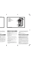
Description of the components
1. Gearmotor
2. Transmission
lever
3. Gearmotor
arm
4. Limit switch adjusting screw when closing
5. Couple release lever
6. Mounting bracket to gate
7. Limit switch adjusting screw when closing
8. Foundation
box
9. Casing
hole
10. Cover fixing screw
11. UNI 5588 M12 nut
12. UNI 6592 12 washer
13. Drainage hole
14. Cable routing hole
15. Pin
Packing lis
t
1. 1 x Gearmotor
2. 1 x UNI 5588 M8 nut
3. 1 x UNI 5739 M4 x 100 screw
4. 1 x Transmission lever
5. 1 x installation manual
www.metalines.com


