background image

FA00150-EN  v.7 - 06/2017 

19 

CAME S.p.A. 


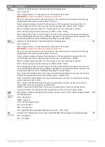
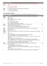
12. ELECTRICAL CONNECTIONS


Rif. 

Code 

Terminals 

Description 


MAINS IN 

Cable for connection to the power supply. 


FUSE F1 

Mains fuse 5x20 – F3,15A 


Electronic control 


MOT 

ENC 

Brushless motor 

Angular sensor 

001FLA-01 

BAT 

Battery power device (001FLA-02 code for Emergency exit) 


FUSE F2 

Battery fuse 5x20 - F16A 

001FLA-03 

LK 

Locking device 


001FLA-04 


Signaling lock position device 

(connected to terminals 1-S1 in Emergency exit automation) 


Summary of Contents for FLUO-SL

Page 1: ...ASSEMBLY AND INSTALLATION MANUAL FLUO SL SLIDING DOOR OPERATOR FA00150 EN EN English ...

Page 2: ...use The safety devices safety sensor photocells etc must be installed taking into account applicable laws and directives Good Working Methods installation premises system operating logic and the forces developed by the motorised door Apply hazard area notices required by applicable regulations Each installation must clearly show the identification details of the automatic pedestrian door 1 2 EC MA...

Page 3: ......

Page 4: ... settings and advanced settings Buttons and Display Buttons and Display Connections to control and safety devices Dedicated connecting terminals Dedicated connecting terminals Power output for accessories 12 Vdc 1 A max 12 Vdc 1 A max Memory for settings and saving Micro SD standard Micro SD standard Function selector device with transponder key 001PBBA04 001PBBA04 required Bistable locking device...

Page 5: ...ed 2 sensors one on each side 3 001FLA 08 Device for fixing sensors 4 001PBBA04 Electronic function selector with transponder key 001FLA 01 001FLA 02 Battery power device for emergency operation 001FLA 03 Bistable locking device complete with release handle 5 Power cable for connection of the automation Note Components and codes are those most commonly used in systems for automatic sliding doors T...

Page 6: ...lapping closes side door depending on the type of used frame system A Ld 2 La 2 350 positioning of the transmission unit maximum size B Ld 2 La 2 340 positioning of the drive unit maximum size C Ld 2 70 positioning of the locking device Length of belt Ld A B 65 x 2 minimum length Code Ld La Lm A max B max C Belt min 001FL2S20 2000 mm 940 mm 2 x 520 mm 180 mm 190 mm 930 mm 3130 mm 001FL2S22 2200 mm...

Page 7: ...La Lm A B max C Belt min 001FL1S20 2000 mm 925 mm 1015 mm 60 mm 575 mm 735 mm 2600 mm 001FL1S22 2200 mm 1025 mm 1115 mm 60 mm 675 mm 835 mm 2800 mm 001FL1S26 2600 mm 1225 mm 1315 mm 60 mm 875 mm 1035 mm 3200 mm 001FL1S30 3000 mm 1425 mm 1515 mm 60 mm 1075 mm 1235 mm 3600 mm 001FL1S33 3300 mm 1575 mm 1665 mm 60 mm 1225 mm 1385 mm 3900 mm 001FL1S36 3600 mm 1725 mm 1815 mm 60 mm 1375 mm 1535 mm 4200 ...

Page 8: ... Lm A B max C Belt min 001FL1S20 2000 mm 925 mm 1015 mm 60 mm 405 mm 905 mm 2940 mm 001FL1S22 2200 mm 1025 mm 1115 mm 60 mm 505 mm 1005 mm 3140 mm 001FL1S26 2600 mm 1225 mm 1315 mm 60 mm 705 mm 1205 mm 3540 mm 001FL1S30 3000 mm 1425 mm 1515 mm 60 mm 905 mm 1405 mm 3940 mm 001FL1S33 3300 mm 1575 mm 1665 mm 60 mm 1055 mm 1555 mm 4240 mm 001FL1S36 3600 mm 1725 mm 1815 mm 60 mm 1205 mm 1705 mm 4540 mm...

Page 9: ...over profile anodized aluminum 4020 mm 001FL CTA6 Cover profile anodized aluminum 6620 mm 107D 001FL G04 Cover gasket 40 m 165 001FL G05 Cover Leaf gasket 40 m Ref Code Description FLUO SL Automation 100 001FL MA4 Support profile anodized aluminum 4020 mm Support profile anodized aluminum 6620 mm 101 001FL MA6 Drive unit profile anodized aluminum 4020 mm Drive unit profile anodized aluminum 6620 m...

Page 10: ... fastening automations Hd and for the calculation of the height of sliding door Hm Note make sure that there is at least 20 mm above the automation to allow the opening of the cover To facilitate the horizontal adjustment of the leaves you can use the fixing door profile as indicated in the figure To make doors with glass doors you can use the fixing profile for glass door as indicated in the figu...

Page 11: ...read by slide the profile rail and seal in the drive unit profile 101 Insert the support gasket 107C in the upper part of the support profile 100 Insert the drive unit gasket 107B at the bottom of the support profile 100 Attach the drive unit profile 101 on the support profile 100 Insert the cover gasket 107D on the drive unit profile 101 Insert the right and the left end caps on profiles already ...

Page 12: ... leaf N B The carriage should be positioned as shown in Chapter 4 Note if the sliding door has a break out system it is necessary to add the second upper wheel on each carriage as indicated in the figure to avoid that very strong pushing of leaf causes the output of the carriage from the rail profile 5 6 Insert the two front brackets mechanical stop near the end caps and secure with the screws In ...

Page 13: ...the cover profile 102 15 mm from the edge as shown in figure If you need insert the cover leaf gasket 165 on the cover profile 102 to reduce the slit bottom of automation Hang the cover profile 102 to the drive unit profile The drive unit profile is kept closed by magnets on the end caps Note To avoid that the cover can be opened without the use of a tool it is necessary to make two 5 mm holes in ...

Page 14: ...screws not supplied by us Note the wall must be straight and smooth otherwise you have to prepare adequate thickness or iron plates on which to secure the support profile FLUO SL or the drive unit profile FLUO SLB to allow for proper levelling 6 2 Attach the automation to the support profile FLUO SL Note if the automation has not been assembled making the assembly of the components as described in...

Page 15: ...liding doors to the carriages by 8MA screws as shown in Chapter 4 Take the doors in the closed position and make adjustments in height and depth Adjust the position of the upper wheels in order to avoid the output of the carriage from the rail profile 104 Handly doors move throughout the race and make sure it moves freely and without friction and that all the wheels are flat on the rail profile 10...

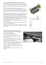
Page 16: ...nnector LK of electronic control using the included cable the excess may be shortened Observe the color of the wires red to red and black to black Switch the unlock rope through present hole on the left end caps until you reach the locking device Switch the rope through the spring and lock making a lap around the bracket With the door in closed position and locked check manually pulling the unlock...

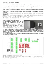
Page 17: ...the absence of mains power the LED remains lit Note it s possible to position the LED on the right end caps making a hole on the suitable area In the absence of mains power battery operation is disabled when the charge level of the battery is too low If desired you can connect a N O contact to reactivate the battery operation example a key switch between the terminals and KY as shown in Figure 9 I...

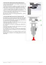
Page 18: ...n black N O blue N C 11 INSTALLATION SIGNALING DEVICE LOCK POSITION 001FLA 04 The microswitch can be fixed to either the locking device 001FLA 03 and both the unlocking device 001FLA 05 using the screws provided 11 1 Connecting the microswitch on locking device 001FLA 03 in automation for emergency exits EMERGENCY Connect the microswitch to terminals of the electronic control using the included ca...

Page 19: ...er supply 2 FUSE F1 Mains fuse 5x20 F3 15A 3 Electronic control 4 MOT ENC Brushless motor Angular sensor 5 001FLA 01 BAT Battery power device 001FLA 02 code for Emergency exit 6 FUSE F2 Battery fuse 5x20 F16A 7 001FLA 03 LK Locking device 8 001FLA 04 Signaling lock position device connected to terminals 1 S1 in Emergency exit automation ...

Page 20: ...airs or replacements of products only original spare parts must be used 12 2 POWER SUPPLY ELECTRICAL CONNECTION Use the supplied cable for connection to electricity The power cable can be connected to an electric plug not supplied by us arranged near the end cap of the automation Drill a hole in the end cap area prepared route the power cord and secure it inside the end cap through the cable tie N...

Page 21: ...owdown of the door in the last 500 mm the safety function of the terminal 6 can be changed using the advanced settings menu Note connect safety devices with test see terminal 41 and remove the jumper 41 6A 41 Output test 12 V Connect the safety devices with test in accordance with EN 16005 as indicated in the following chapters Note in case of devices without test connect the N C contact to termin...

Page 22: ... automatic operation of the door is with a partial opening of the leaves Automatic one way operation When selected the symbol lights up and automatic operation of the door is in one way mode Function selector is not active The symbol lights up when the function selector is not active To activate the temporary operation of the function selector is necessary to approach the badge to the logo or sele...

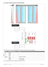
Page 23: ...R8204 Connect the sensor using the supplied cable to the terminals of the electronic control as follows CB01 001MR8204 sensor Notes OPENING 0 Brown 1 Green 1 Yellow 3A 3B White SAFETY 0 Blue 1 Pink 8A 8B Gray Remove the jumper 41 Red For more information check the installation manual of the sensor ...

Page 24: ...ws CB01E 001MR8700 sensor output current Notes OPENING 0 Brown 1 Green R0 White Black Remove the jumper R1 Yellow Black Remove the resistor SAFETY 0 Blue 1 Pink 8A Gray Remove the jumper 41 Red White Do not connect Yellow Do not connect Connect the sensor B side using the supplied cable to the terminals of the electronic control as indicated in Section 12 5 For more information check the installat...

Page 25: ... the sensor using the supplied cable to the terminals of the electronic control as follows CB01 001MR8701 sensor Notes SAFETY 0 Brown 0 Blue 1 Green 1 Pink 6A 6B Gray Remove the jumper 41 Red Yellow Do not connect White Do not connect For more information check the installation manual of the sensor ...

Page 26: ...tes OPENING 0 Green 1 Brown 1 White 3A 3B Yellow For more information check the installation manual of the sensor 12 9 ELECTRICAL CONNECTION OF PHOTOCELL 001FLA 17 Connect the photocell using the cables supplied to the terminals of electronic control as follows Terminals PE12CNT15 emitter grey cable PE12CNT15PO receiver black cable Notes SAFETY 0 Blue BU Blue BU 1 Brown BN Brown BN 8A 8B Black BK ...

Page 27: ... POWER terminal 1 COM terminal 1 NO terminal 3A or 3B For more information check the installation manual of the sensor 12 11 ELECTRICAL CONNECTION OF TRANSPONDER PROXIMITLY READER 001TSTM1 Connect the badge reader to terminals of the electronic control as follows black wire terminal 0 red wire terminal 1 white wire terminal 1 white wire terminal KO For more information refer to the installation ma...

Page 28: ...ECTION Setting the opening direction Choose between the following values 2 leaves door or 1 leaf door opening to right 1 leaf door opening to left EMERGENCY In the case of 1 leaf Emergency automation with opening on the left the carriage must be fixed to the belt at the top as indicated in chapter 15 1 PART PARTIAL OPENING Setting the percentage of partial opening Choose between the minimum and ma...

Page 29: ...t the following memory management menu Display Description Factory settings FSET FACTORY SETTINGS Restore all settings to factory defaults Choose between the following values NO no restore YES restore to factory settings NO FW FIRMWARE UPGRADE Programming procedure of electronic control Insert the micro SD memory in the electronic control From this menu choose the firmware version you want Press E...

Page 30: ...ic operation and unidirectional EMERGENCY Automatic setting for Emergency automation LOCK always locked the door closed AUTO PUCL PUSH DOOR CLOSED Setting the push on the closed mechanical stop Choose between the following values NO no push MIN light push MED medium push MAX heavy push MIN PIPP PUSH DOOR OPEN Setting of the opening push Choose between the following values NO no push YES push enabl...

Page 31: ...tomatic setting command of function selector The closing and the opening of the 1 G2 contact changes the function selector mode see menu SEL SAM1 and SEL SAM2 EMER Emergency opening contact N C The opening of the 1 G2 contact opens the door PART Partial opening contact N O see menu MENU PART 10 90 CAB Step by step contact N O The closing of the 1 G2 contact performs in sequence the closing of the ...

Page 32: ... DELAY CLOSED DOOR Setting delay time function closed door Choose between the minimum and maximum values minimum value 1 s maximum value 5 min 1 TMEM TAG MEMORISE Saving procedure of badge and numeric code for function selector Choose between the following values NO no saving SMOD Saving badge and numeric code for activation of the function selector press the ENTER button for 1 second the display ...

Page 33: ...he end of the storage procedure Note if the badge and the numeric code is not stored the buzzer emits no beeps NO TERA TAG TOTAL ERASE How to erase all stored badges and numeric codes Choose between the following values NO no erase YES cancellation of all badges and numeric codes NO SAM1 SELECTOR AUTOMATIC MODE First setting of function selector when the 1 G1 1 G2 contact becomes closed Set the me...

Page 34: ... bistable locking device and microswitch Choose from the following values NO the symbol closed door remains lit even if the door is opened by hand YES the symbol closed door lights up only when the door is really closed and locked Note if the locking device does not close the door the symbol closed door flashes NO 13 5 INFORMATION AND DIAGNOSTICS MENU Using the buttons and select INFO press ENTER ...

Page 35: ...econds Check the connection to the terminal KC W100 Programming error CB01 Repeat the programming procedure in MEM FW menu W103 Programming error FSD1 Repeat the programming procedure in SEL FW menu W104 Programming error CB02 Repeat the programming procedure in MEM FW menu W127 Automation reset The automation performs a self test W128 on No power supply Check the power supply W129 1 No battery Ch...

Page 36: ...verify the correct operation of the door Note the automation automatically detects any obstacles during the closing movement reversal movement and opening stopping movement 14 6 Connect one at a time opening and safety devices to protect the closing cycle of the door as described in Chapter 12 5 and verify proper operations Note verify that the opening access is properly protected by safety sensor...

Page 37: ...ovement and opening stopping movement 15 6 Connect one at a time opening and safety devices to protect the closing cycle of the door as described in Chapter 12 6 and verify proper operations Note verify that the opening access is properly protected by safety sensors in accordance with the requirements of the European standard EN16005 annex C 15 7 Connect one at a time safety devices to protect the...

Page 38: ...perform false detections or the presence of moving objects in the field of action The automatic closing doesn t work Check the settings of the function selector Safety devices not activating Incorrect connections between the safety devices and electronic control Check that the safety contacts of the devices are properly connected to the terminal blocks and the relative jumpers have been removed Th...

Page 39: ... carriage wheels if necessary replace them Check the correct fitting of the doors on the carriages If present verify proper engagement of the locking device and the operation of the release cord Every 6 months or every 500 000 cycles Connect the power supply and perform the following checks and adjustments Check the correct operation of the control devices and safety Check the detection area of th...

Page 40: ...son di Casier Treviso Treviso Italy 33079 Sesto al Reghena Sesto al Reghena Pordenone Pordenone Italy 39 0422 4940 39 0422 4941 39 0434 698111 39 0434 698434 s a f e t y c o m f o r t English Manual code FA00150 EN v 7 06 2017 Came S p A The data and information in this manual may be changed at any time and without notice ...

Reviews: