


Manufacturer’s declaration
Declaration of conformity
la CAME Cancelli Automatici S.p.A.
via Martiri della Libertà, 15
31030 Dosson di Casier - Treviso - ITALY
tel
(+39) 0422 4940 - fax (+39) 0422 4941
internet: www.came.it - e-mail: [email protected]
Declare under their own responsibility that the following
products for gate and garage door automation called:
Are compliant with essential requirements and with pertinent
regulations established by the following directives and to the
applicable parts of the standards listed below:
Electromagnetic compatibility directive
2004/108/CE
Electrical equipment designed for use within certain voltage
limits directive
2006/95/CE
EN 61000-6-
1
EN 61000-6-
2
EN
61000-6-3
EN 60
335-1
EN
13241
-1
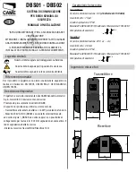
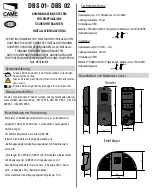
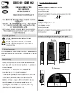
DBS01- DBS02
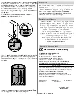
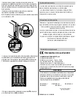
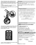
Demolition and Disposal
PRODUCT DISPOSAL – Our products and packaging are made
up of various types of materials. Most of them (paper, plastics,
etc.) may be disposed of in normal garbage collection bins and
can be recycled by disposing of in specifi c recyclable material
collection bins and disposal in authorized centres.
Batteries and any other materials containing hazardous
substances, however, should be removed and given to qualifi ed
service companies for proper disposal.
Prior to disposal, it is always advisable to check specifi c
regulations in force in the place of disposal.
PLEASE DISPOSE OF PROPERLY!
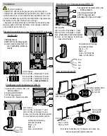
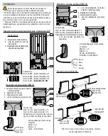
K
K
K
1 2 3 4 5 6 7 8 9 10 11 12 1 2 3 4 5 6 7 8 9 10 11 12
05 06 07 08 09 V1 V2 V305 06 07 08 09 V1 V2 V3
1,5V AAA1,5V AAA
++
--
++
--
--
++
--
++
1,5V AAA1,5V AAA
R13R13
R15R15
R22R22
R23R23
6!!!
6!!!
6!!!
6!!!
./
./ # .#
.#
K
K
K
1 2 3 4 5 6 7 8 9
10 11 12
05 06 07
08 09 V1
V2 V3
1,5V AAA
+
-
+
-
1,5V AAA
R13
R15
R22
R23
4
3
2
1
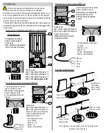
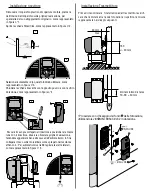
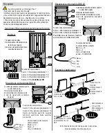
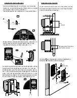
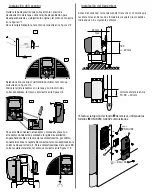
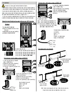
• Choose the point where the cable should go through, either
making a hole in the bottom of the Receiver and the gate door
or have it go through along the side, making a hole on the
edge of the transmitter’s cover and then passing it through
the hollows of the sensitive edge’s mounting bracket.
• Connect the safety sensitive edge as per the instructions in
the package.
N.B. the transmitter should be connected to the safety
sensitive edge with contact C.- N.C
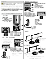
• Close the device, hooking the cover on from the top and
use the supplied screws to secure it in place.
• Once it has been connected to the sensitive edge, select the
photodiode (see the method and examples on page 2) and
install the batteries (4 x 1.5V AAA) checking the polarity on
the board.
L’amministratore delegato
Sig.
Gianni Michielan
119RU84 ver 0.2 - 03/2009
Malfunction
- The two LED indicators fl ashing on the Receiver mean transmit-
ter dead batteries.
- The two LED indicators giving off steady light on the Receiver
means that the signal has been interrupted, that there is a
transmitter malfunction or that the system has been activated
following the installation of the sensitive edge.


