background image

MECHANICAL

ADJUSTMENTS

~--_

..

_--

--'1

----------

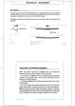
~BELT SUPPORT

The belt support is used to control belt vibration. It is installed at the centre of automation
systems powering two door wings whose support profile exceeds 3020 mm in length. If

necessary. the support may be bent into the required shape.

N.B. Make sure that the belt support does not come into contact with moving parts during

operation .

.:'-\!

;

j-' ----."

-j

•.L'T~

Moullng

screw

fr:

----

- -~:-:~:~~.l-

- - - -

- - - - - - - -:..

- - - --

----.\\:\>:<::

-------

............•..

__

.

(..-~'~".'. '-'+>";'.,~,

\

'\~~~I_SUPport

. _._

_.~

".j , .•

-

..1

~~-

.-.-

';.'

••........•......•..........•

,

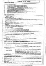
CHECKING FOR PROPER ASSEMBLY

After the beam has been installed and all mechanical

adjustments have been made, made sure that:

_ no scraps of materials left by manufacturing

processes

remain on the guide track, which would damage the track

and/or the trolley wheels;

_ no foreign objects and/or tools have been left on the inside

of the beam;

_ the door wings are properly aligned and the mechanical

stops have been correctly positioned as described above.

Before applying power to the automation system, check for
proper operation by opening and closing the system manually
(push directly on the door wings to perform this check),

--~

"

Summary of Contents for Corsa Series

Page 1: ...TION SYSTEM FOR SLIDING DOORS Ooeumorrtal lono e nIao M70 fCW 3 1 07f2000 eCAME CAJI Cf UI AUTOIllA j119PM70 AUTOMATION SYSTEM FOR SLIDING DOORS WITH MICROPROCESSOR CONTROL for door wings weighting I...

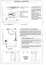
Page 2: ..._ The trolleys can be used to adjust the alignment of the door wings as follows vertical adjustment RV with bolts and nuts A and B transverse adjustment RT with bolts and nuts C horizontal adjustment...

Page 3: ...RSE ADJUSTMENT R The vertical plane of the rollers on the trolleys must be parallel with the beam If the trolleys are out of alignment i e if the door wing does not slide easily proceed as follows Loo...

Page 4: ...vents the optional profile housing from oscillating and bending longitudinally One bracket can be installed when the beam is mounted at a height of up to 2 80 m while both brackets should be installed...

Page 5: ...1 CHECKING FOR PROPER ASSEMBLY After the beam has been installed and all mechanical adjustments have been made made sure that _ no scraps of materials left by manufacturing processes remain on the gu...

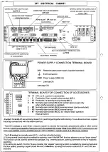
Page 6: ...l sensor ean be excluded S R2 2 R2 Normally open contact N O internal sensor Rl 2 M Normally open contact N O for step by step operation 2 manual bullon l Contact 1 2 and 2 C1 are normally closed N C...

Page 7: ...mains power has been disconnected and the red power terminal has been removed from the emergency battery if installed ADJUSTMENT TRIMMERS II 0 111 MF9011 MF9111 11 II I 4 API ARZ lOA V RA LCH ADJUSTME...

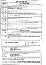
Page 8: ...ION FUNCTIONS 1 ON Activation of spring loaded anti panic device set dip switch 4 to ON constant push while closing 1D dip function selector see pag 19 2 Not used keep the dip in position OFF 3 ON Exc...

Page 9: ...stem to re arm the electric lock if installed I If the automation system stops during the closing cycle the motor polarity may be incorrect If this occurs proceed as follows Disconnect the mains power...

Page 10: ...Mf9011 MF9111 illI1 llfl L_ _ __ __ Anti panic device with constant battery control Note in case the MA7041 selector is not connected and you wish to activate the anti panic function bond contacts 1 3...

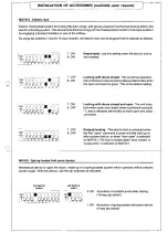
Page 11: ...n command is given This is the default selling Locking with doors closed and open The unit locks both when open and closed when positioned correctly and is released electrically by each open and close...

Page 12: ...Mechanical interference is occurring between moving door wings and non movin l parts for example door wings pavement non moving door wings mOVing door wings moving door wings pavement mounted guides w...

Reviews: